
TM 5-3805-255-14
0096
CLEANING AND INSPECTION CONTINUED
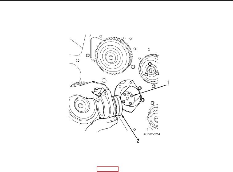
6. Inspect thrust bearing hub (Figure 8, Item 2) and thrust face of camshaft (Figure 8, Item 1) for wear. Replace
parts as necessary.
Figure 8. Camshaft Thrust Hub and Face Inspection.
0096
7. Inspect camshaft bushings for wear, and if replacement is necessary, proceed as follows:
a. Remove flywheel housing and flywheel (WP 0091).
b. Pull or press bushings from position.
c.
Inspect bushing bores in crankcase for burrs or damage.
8. Align oil holes in bushings with oil holes in crankcase and install bushings into crankcase.
9. Two bushings in thrust bearing hub must be pressed in from outside of hub bore until outer edges of bushings
are flush with hub. This provides a channel between two bushings for lubricating oil to gear train and front main
bearing.
10. Inspect valve tappets. Replace any valve tappets that are scuffed, scored, or cracked. If one or more valve
tappet faces are badly chipped, install new camshaft.
END OF TASK
0096-9