
TM 5-3805-255-14
0096
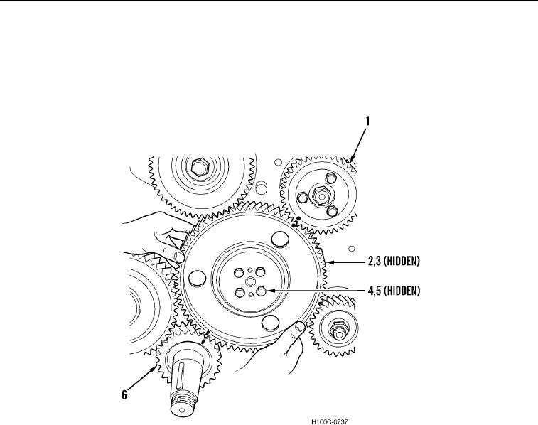
INSTALLATION CONTINUED
3. Install camshaft drive gear (Figure 11, Item 2) so timing marks on crankshaft gear (Figure 11, Item 6), camshaft
drive gear, and injection pump drive gear (Figure 11, Item 1) are aligned.
4. Install four new camshaft drive gear lockwashers (Figure 11, Item 5) and bolts (Figure 11, Item 4) on camshaft
thrust hub (Figure 11, Item 3). Torque bolts to 90 lb-ft (122 Nm).
Figure 11. Camshaft Drive Gear Installation.
0096
0096-11