
TM 5-3805-255-14
0097
REMOVAL CONTINUED
NOTE
The crankcase oil pan must be removed in order to disconnect lube oil suction line from
front cover.
2. Remove oil pan with scavenging pump manifold attached.
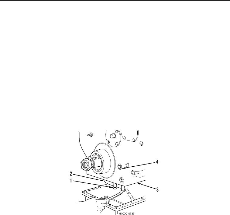
3. Remove two bolts (Figure 2, Item 1) and lube oil suction pipe (Figure 2, Item 2) from front cover (Figure 2,
Item 3).
WARNING
Use extreme caution when handling heavy parts. Provide adequate support and use
assistance during procedure. Ensure that any lifting equipment is in good condition and of
suitable load capacity. Keep clear of heavy parts supported by lifting equipment. Failure to
follow this warning may result in injury or death to personnel.
4. Remove bolts (Figure 2, Item 4) from front cover (Figure 2, Item 3) and crankcase. Be sure to remove two bolts
and locks located in fan drive housing opening of front cover. Attach a suitable lifting device to front cover and
remove front cover from engine.
5. Remove crankshaft gear nut (Figure 2, Item 1) and oil flinger (if equipped) (Figure 2, Item 2).
Figure 2. Front Cover Removal.
0097
0097-3