TM 5-3805-255-14
0101
FAN MOUNTING DISASSEMBLY
000101
1. Support fan mounting assembly in a press using coupling flange support tool (WP 0125).
CAUTION
Make sure support tool slips through slots in rear of pulley and supports coupling flange
only. Failure to follow caution may result in damage to equipment.
2. If necessary, fabricate Belleville spring compressing tool (WP 0125).
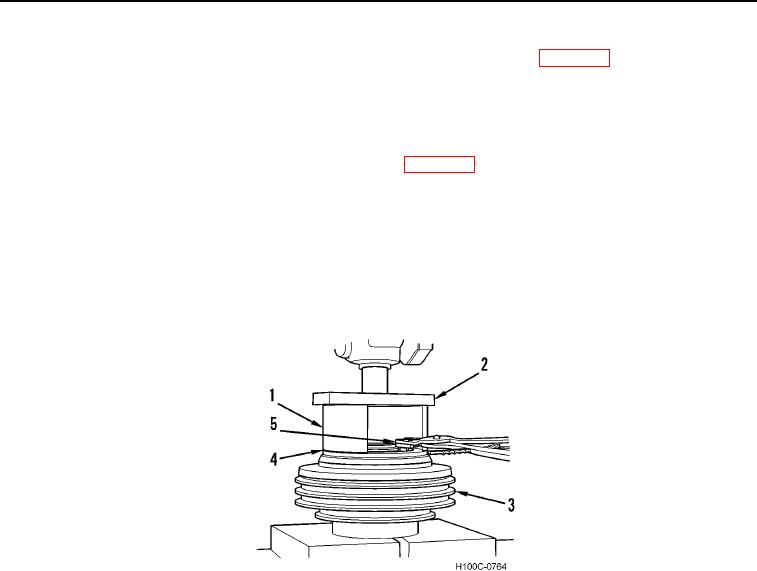
3. Place Belleville spring compressing tool (Figure 3, Item 1) on top of fan mounting assembly (Figure 3, Item 3).
4. Place a steel bar (Figure 3, Item 2) across top of Belleville spring compressing tool and compress Belleville
spring (Figure 3, Item 4).
5. Remove snap ring (Figure 3, Item 5) from fan mounting assembly (Figure 3, Item 3) using snap ring pliers.
6. Slowly release pressure of press on Belleville spring (Figure 3, Item 4).
7. Remove fan mounting assembly (Figure 3, Item 3) from press.
Figure 3.
Snap Ring Removal.
0101
END OF TASK
INSPECTION AND REPAIR
000101
1. Refer to dimensional drawing (Figure 4) and replace any part that does not meet specifications.
2. Check dimensions in more than one area and watch for unusual wear patterns.
NOTE
Dimensional drawing is of latest fan mounting assembly only. It is recommended that parts
be inspected for wear and replaced with new. Check all parts for gouging caused by
spinning against mating part. Replace part if worn beyond specification or gouged.
3. Check snap ring (Figure 4, Item 1), Belleville springs (Figure 4, Item 3), spacer (Figure 4, Item 2), Belleville
spacer (Figure 4, Item 4), mounting flange (Figure 4, Item 7), and pressure plate (Figure 4, Item 5) for bluing or
gouging. Replace if present.
4. Inspect pressure plate (Figure 4, Item 5) tangs and coupling flange/pulley assembly (Figure 4, Item 9) keyways
for pounding and wear. Replace if wear is beyond specifications.
5. Replace friction discs (Figure 4, Item 6) and friction bearing (Figure 4, Item 8) every time fan mounting
assembly (Figure 4, Item 10) is disassembled for service.
0101-4

