
TM 5-3805-255-14
0100
INSTALLATION CONTINUED
NOTE
Remove plug located on top of injection pump adapter housing so injection pump gear is
visible for timing procedure.
13. Rotate drive gear to bring mark on injection pump gear into alignment with pointer on pump and tighten three
drive gear bolts evenly.
14. Rotate engine crankshaft counterclockwise (as viewed from fan drive end) to about 60 degrees before top
dead center (BTDC) of No. 1 cylinder and bring it back clockwise to 38 degrees BTDC.
15. Check timing pointer to be sure it lines up with mark on gear. If pointer is not aligned, loosen bolts on drive gear
and align. Retighten bolts.
16. Install plug on pump adapter housing.
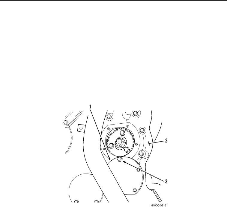
17. Install new gasket on injection pump timing cover (Figure 16, Item 1). Position timing cover on crankcase front
cover (Figure 16, Item 2). Install five bolts (Figure 16, Item 3) and tighten bolts securely in alternating pattern.
Figure 16. Injection Pump Timing Port.
0100
0100-12