
TM 5-3805-255-14
0102
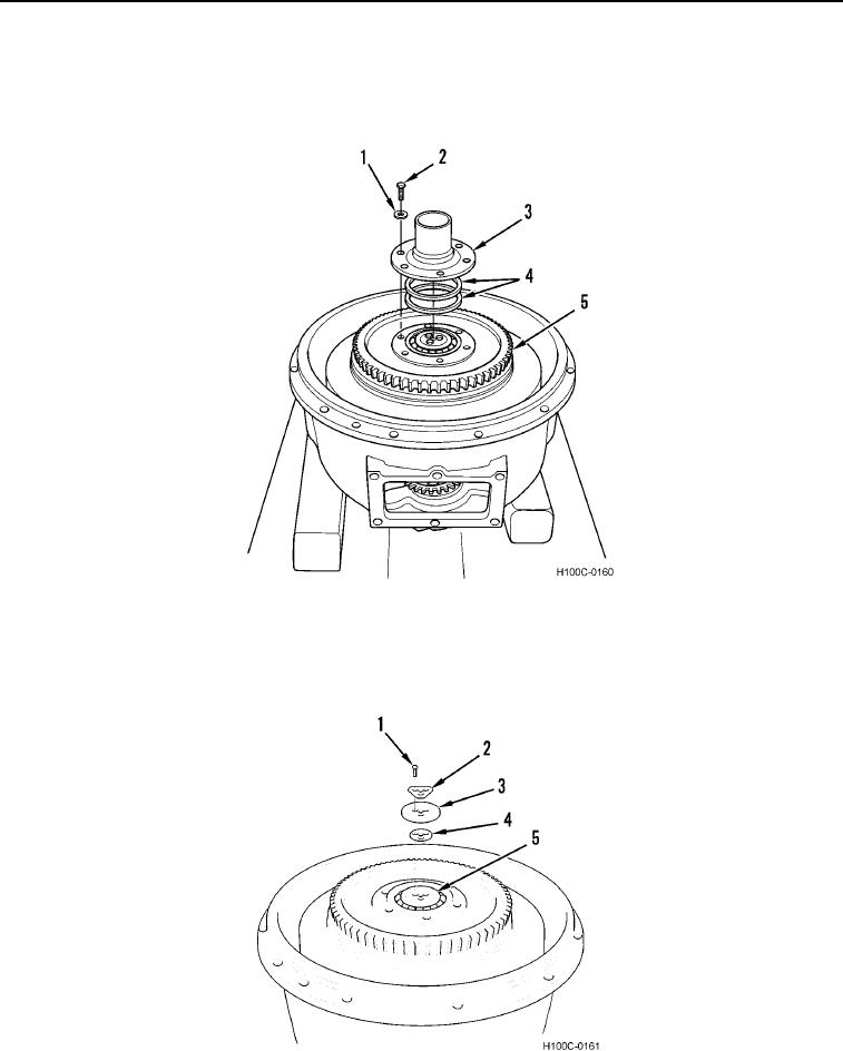
DISASSEMBLY CONTINUED
4. Remove six capscrews (Figure 4, Item 2), lockwashers (Figure 4, Item 1), hub (Figure 4, Item 3), and shims
(Figure 4, Item 4) from converter assembly (Figure 4, Item 5). Tie input hub shims together to facilitate
assembly. Discard lockwashers.
Figure 4. Hub and Shims Removal.
0102
5. Remove three bolts (Figure 5, Item 1), lockplate (Figure 5, Item 2), retaining washer (Figure 5, Item 3), and
shims (Figure 5, Item 4) (if used) from output shaft (Figure 5, Item 5). Discard lockplate.
Figure 5. Retaining Washer and Shim Removal.
0102
0102-4