
TM 5-3805-255-14
0102
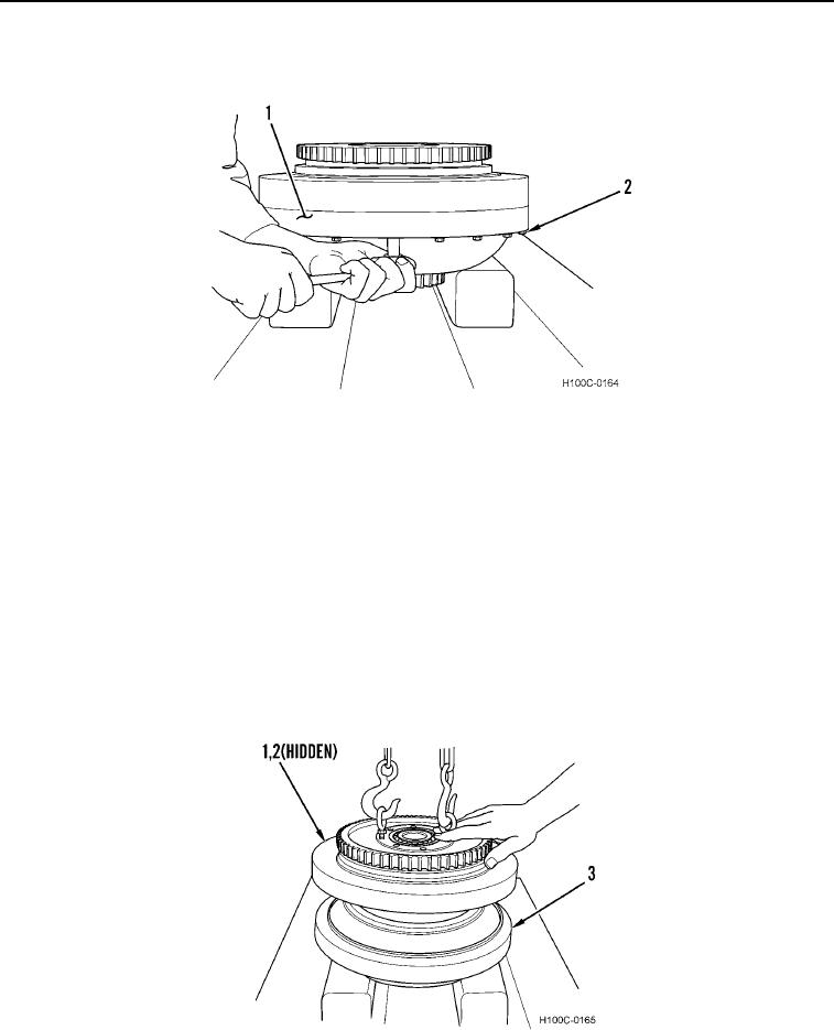
DISASSEMBLY CONTINUED
8. Remove 24 capscrews (Figure 8, Item 2) from converter assembly (Figure 8, Item 1).
Figure 8. Converter Separation.
0102
WARNING
Use extreme caution when handling heavy parts. Provide adequate support and use
assistance during procedure. Ensure that any lifting device is in good condition and of
suitable load capacity. Keep clear of heavy parts supported by lifting device. Failure to
follow this warning may result in injury or death to personnel.
NOTE
Do not drop turbine as it is removed from converter assembly
9. Use a suitable lifting device to lift drive housing (Figure 9, Item 1) and turbine (Figure 9, Item 2) from converter
assembly (Figure 9, Item 3).
10. Invert drive housing (Figure 9, Item 1) and turbine (Figure 9, Item 2) and remove turbine from drive housing.
Figure 9. Turbine Removal.
0102
0102-6