
TM 5-3805-255-14
0102
DISASSEMBLY CONTINUED
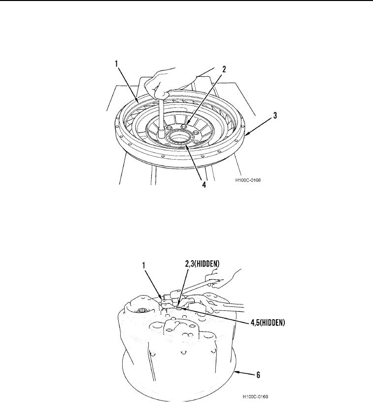
14. Remove seven bolts (Figure 12, Item 2) from drive gear (Figure 12, Item 1).
15. Remove bearing (Figure 12, Item 4) and drive gear (Figure 12, Item 1) from impeller (Figure 12, Item 3).
Figure 12. Accessory Drive Gear Removal.
0102
16. Position converter housing (Figure 13, Item 6) with output yoke (Figure 13, Item 1) facing up.
17. Remove three capscrews (Figure 13, Item 2), lockplate (Figure 13, Item 3), retaining washer (Figure 13,
Item 4), and output yoke (Figure 13, Item 1) from output shaft (Figure 13, Item 5). Discard lockplate.
Figure 13. Yoke Removal.
0102
0102-8