
TM 5-3805-255-14
0103
DISASSEMBLY CONTINUED
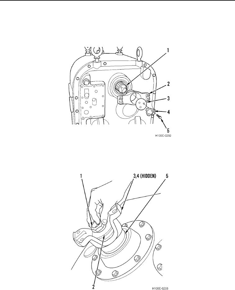
2. Bend back tabs of locking plate (Figure 2, Item 4). Remove three bolts (Figure 2, Item 5), locking plate (Figure
2, Item 4), retaining washer (Figure 2, Item 3), and yoke (Figure 2, Item 2) from input shaft (Figure 2, Item 1).
Discard locking plate.
Figure 2. Input Yoke Removal.
0103
3. Remove output locknut (Figure 3, Item 1), washer (Figure 3, Item 2) and O-ring (Figure 3, Item 4) from output
shaft (Figure 3, Item 5). Remove yoke (Figure 3, Item 3) from output shaft (Figure 3, Item 5). Discard O-ring.
Figure 3. Output Yoke Removal.
0103
0103-3