TM 5-3805-255-14
0102
ASSEMBLY CONTINUED
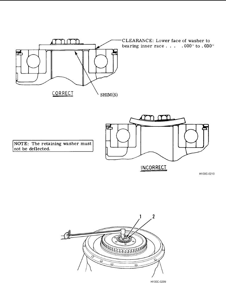
49. Add or subtract shims beneath retaining washer until clearance between washer and bearing is within
recommended limits of 0.000 to 0.030 in. (0.000 to 0.763 mm) (Figure 53).
Figure 53. Clearance Determination.
0102
50. When proper clearance is obtained, torque three capscrews (Figure 54, Item 1) to 26 to 32 lb-ft (35 to 43 Nm).
Bend up tabs on lockplate (Figure 54, Item 2).
Figure 54. Locking Plate Installation.
0102
0102-32

