
TM 5-3805-255-14
0103
DISASSEMBLY CONTINUED
WARNING
Use extreme caution when handling heavy parts. Provide adequate support and use
assistance during procedure. Ensure that any lifting equipment is in good condition and of
suitable load capacity. Keep clear of heavy parts supported by lifting equipment. Failure to
follow this warning may result in injury or death to personnel.
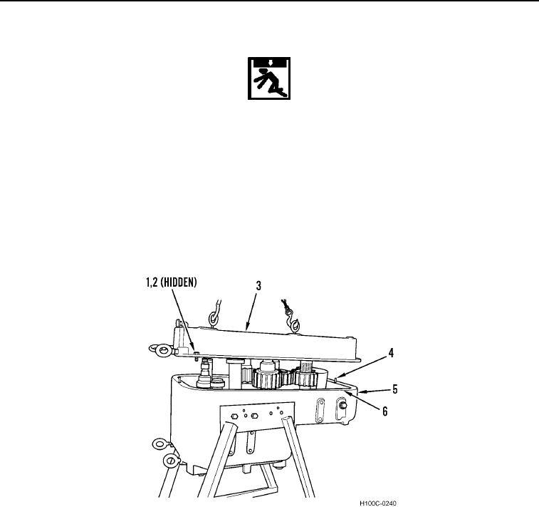
12. Attach suitable lifting device to rear cover (Figure 10, Item 3).
13. Remove 30 bolts (Figure 10, Item 1), lockwashers (Figure 10, Item 2), and rear cover (Figure 10, Item 3) from
transmission housing (Figure 10, Item 5).
14. Remove two dowels (Figure 10, Item 4) from transmission housing (Figure 10, Item 5).
15. Remove gasket (Figure 10, Item 6) from transmission housing (Figure 10, Item 5). Discard gasket.
16. Remove lifting device.
Figure 10. Rear Cover Removal.
0103
0103-7