
TM 5-3805-255-14
0103
DISASSEMBLY CONTINUED
WARNING
Use extreme caution when handling heavy parts. Provide adequate support and use
assistance during procedure. Ensure that any lifting equipment is in good condition and of
suitable load capacity. Keep clear of heavy parts supported by lifting equipment. Failure to
follow this warning may result in injury or death to personnel. In event of injury, seek
medical attention.
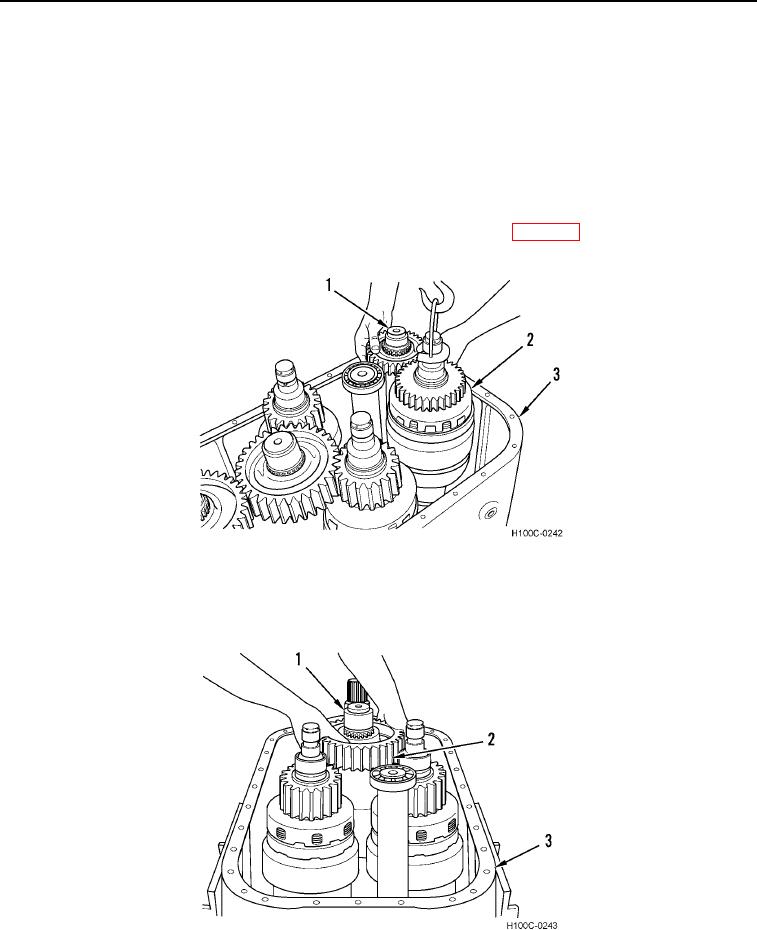
18. Install clutch pack lifting tool to forward-reverse clutch pack (Figure 12, Item 2) in oil supply groove. Using a
suitable lifting device, lift clutch pack and reverse idler shaft assembly (Figure 12, Item 1) from transmission
housing (Figure 12, Item 3). For clutch pack overhaul procedure refer to (WP 0104). Remove lifting device.
Figure 12. Clutch Pack and Reverse Idler Shaft Removal.
0103
19. Remove low speed gather gear (Figure 13, Item 2) to remove shaft assembly (Figure 13, Item 1) from trans-
mission housing (Figure 13, Item 3).
Figure 13. Gather Shaft Assembly Removal.
0103
0103-9