
TM 5-3805-255-14
0103
DISASSEMBLY CONTINUED
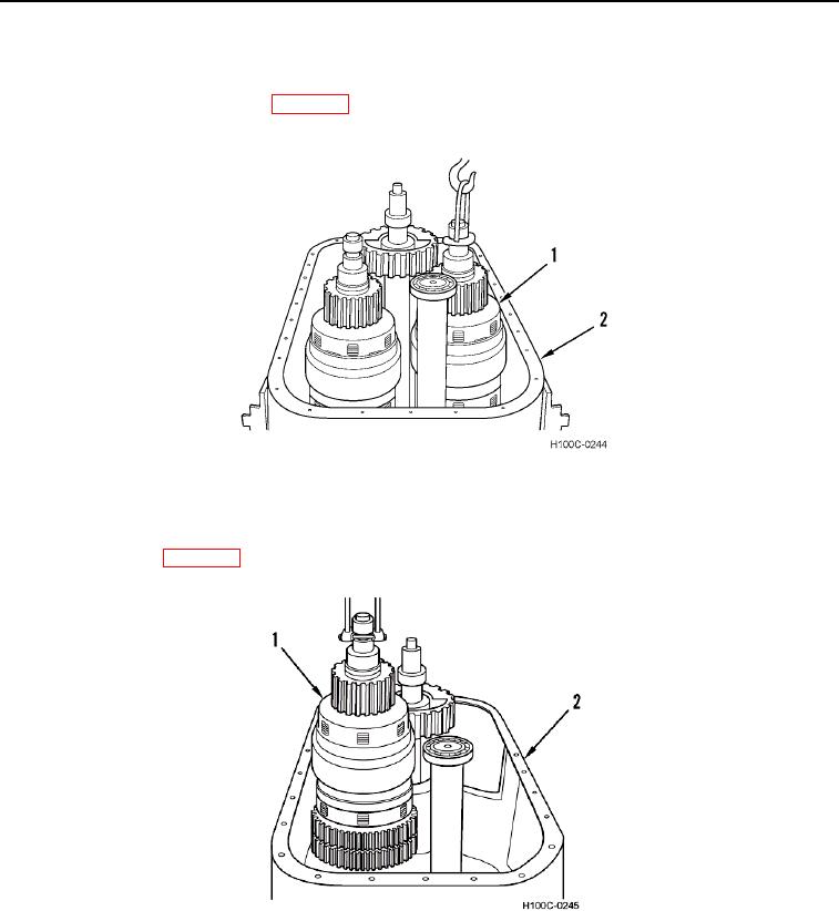
20. Attach special lifting tool to 2nd and 4th clutch pack (Figure 14, Item 1) oil supply groove and use suitable lifting
device to remove clutch pack (Figure 14, Item 1) from transmission housing (Figure 14, Item 2). For clutch
pack overhaul procedure refer to WP 0104.
Figure 14. 2nd and 4th Clutch Pack Removal.
0103
21. Attach clutch pack lifting tool to 1st and 3rd clutch pack (Figure 15, Item 1) in oil supply groove and use suitable
lifting device to remove clutch pack from transmission housing (Figure 15, Item 2). For clutch pack overhaul
procedure refer to WP 0104.
Figure 15. 1st and 3rd Clutch Pack Removal.
0103
0103-10