
TM 5-3805-255-14
0116
DISASSEMBLY
000116
CAUTION
Place gear housing in a suitable holding device. Do not apply excess pressure to housing.
Failure to follow this caution may result in damage to component.
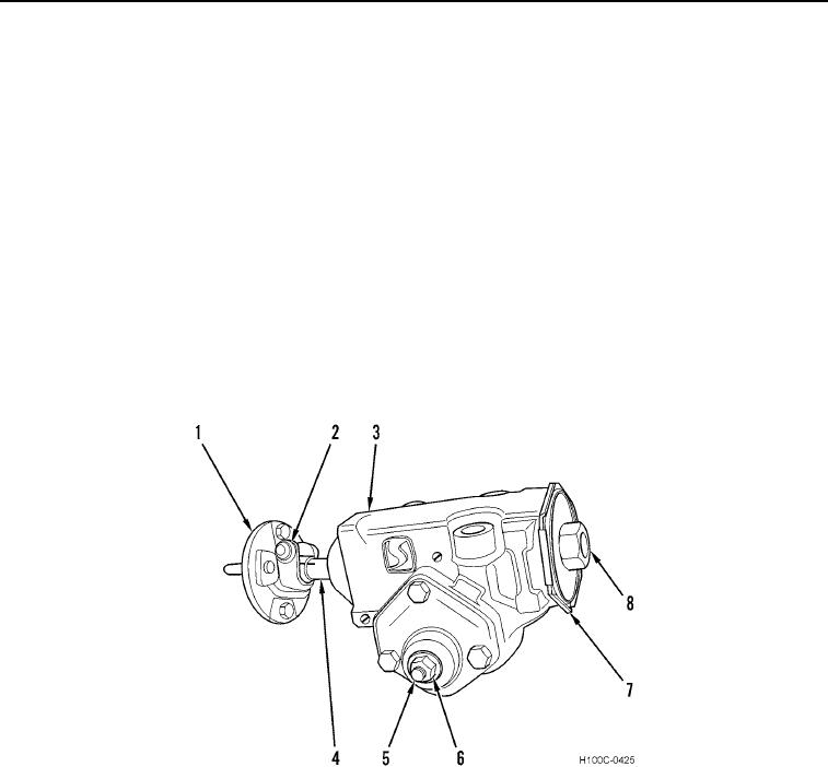
1. Place gear assembly (Figure 1, Item 3) in suitable holding device.
2. Mark on worm shaft (Figure 1, Item 4) in line with reference indicator on flange (Figure 1, Item 1) to insure
proper positioning of parts during assembly.
3. Remove flange bolt (Figure 1, Item 2) and flange (Figure 1, Item 1) from gear assembly (Figure 1, Item 3).
4. Loosen nut (Figure 1, Item 6) from lash adjuster screw (Figure 1, Item 5).
CAUTION
Remove load from worm bearing. Failure to comply may result in damage to equipment.
5. Turn lash adjuster screw (Figure 1, Item 5) three turns counterclockwise.
6. Loosen bearing adjuster nut (Figure 1, Item 7) and remove bearing adjuster (Figure 1, Item 8).
Figure 1. Steering Gear.
0116
0116-2