
TM 5-3805-255-14
0116
ASSEMBLY
000116
NOTE
All parts must be kept clean. Grease and oil used during assembly must be free from dirt
or other contaminants. Prelubricate all bearings and moving parts with lubricating fluid.
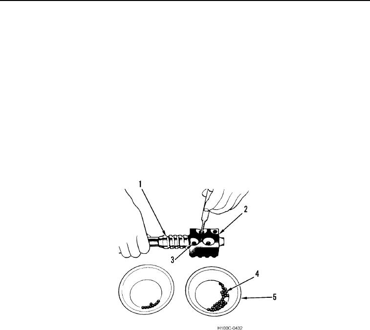
1. Place worm shaft assembly (Figure 7, Item 1) horizontal on clean work bench. Place ball nut (Figure 7, Item 2)
over worm with return guide holes (Figure 7, Item 3) in ball nut facing up. Align groove in worm and ball nut by
sight.
2. Count and place half of balls (Figure 7, Item 4) in a clean container (Figure 7, Item 5).
3. Drop balls into one of the ball return guide holes (Figure 7, Item 3). Slowly rotate worm (Figure 7, Item 1) away
from hole while inserting balls. Continue until circuit is filled from bottom of hole to bottom of the other or until
stopped by reaching end of worm.
4. If balls are stopped at end of worm shaft (Figure 7, Item 1), hold down balls already installed with rod or punch.
Rotate worm shaft in a reverse direction a few turns. Filling of circuit may then be continued. It may be
necessary to work worm shaft back and forth holding balls down first in one hole and then in the other. This will
close-up spaces between balls, filling the circuit completely.
Figure 7. Worm and Ball Nut Assembly.
0116
0116-7