
TM 5-3805-255-14
0116
REPAIR
000116
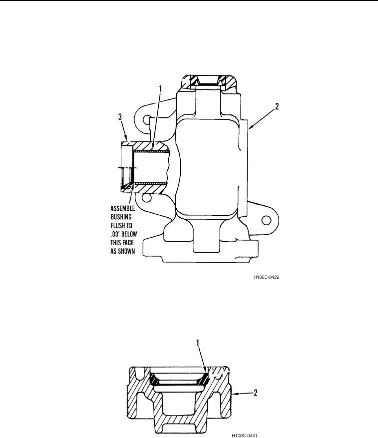
1. Remove pitman shaft bushing (Figure 5, Item 1) from housing (Figure 5, Item 2).
2. Install new shaft bushing (Figure 5, Item 1) in position. Press bushing flush with edge of housing bore (Figure
5, Item 3).
Figure 5. Housing Bushing and Seal Replacement.
0116
3. Remove cup (Figure 6, Item 1) from adjuster (Figure 6, Item 2).
4. Install a new cup (Figure 6, Item 1) in adjuster (Figure 6, Item 2) using a minimum of 7,000 lb (17,792 Nm)
force to seat cup.
Figure 6. Adjuster Cup Replacement.
0116
END OF TASK
0116-6