TM 5-3805-255-14
0119
DISASSEMBLY CONTINUED
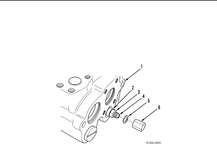
13. Remove nut (Figure 8, Item 6) and washer (Figure 8, Item 5) from control valve (Figure 8, Item 1). Discard
washer.
NOTE
Mark position of adjusting screw before disassembly, for ease of installation.
14. Hold adjusting screw (Figure 8, Item 4) and loosen jamnut (Figure 8, Item 3). Remove adjusting screw and
washer (Figure 8, Item 2). Discard washer.
Figure 8. Adjusting Screw Assembly Removal.
0119
0119-5

