TM 5-3805-255-14
0119
ASSEMBLY CONTINUED
000119
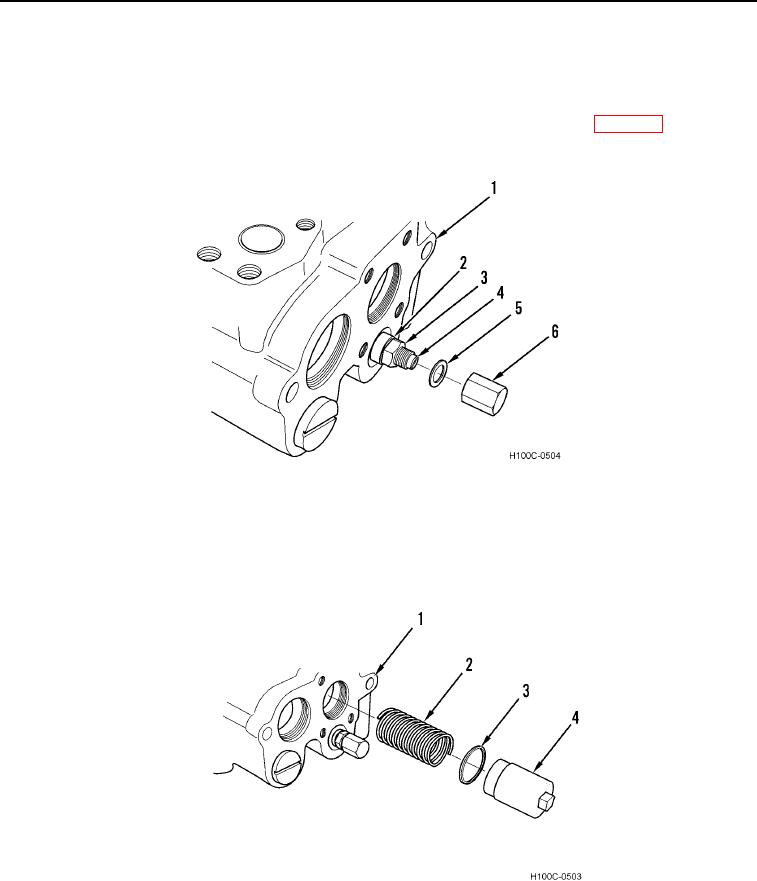
7. Install adjusting screw (Figure 14, Item 4) in valve (Figure 14, Item 1). Turn screw in to approximate position at
time of disassembly.
8. Install new washer (Figure 14, Item 2) and jamnut (Figure 14, Item 3).
9. Install new washer (Figure 14, Item 5) and nut (Figure 14, Item 6) finger tight. Refer to WP 0072 for correct
adjustment procedure.
Figure 14. Adjusting Screw Installation.
0119
10. Lubricate new seal ring (Figure 15, Item 3) with technical petrolatum and install on cap (Figure 17, Item 4).
11. Install spring (Figure 15, Item 2) in valve (Figure 15, Item 1).
12. Install cap (Figure 15, Item 4) on valve (Figure 15, Item 1) and tighten securely.
Figure 15. Cap Installation.
0119
0119-9

