
TM 5-3805-255-14
0119
ASSEMBLY CONTINUED
000119
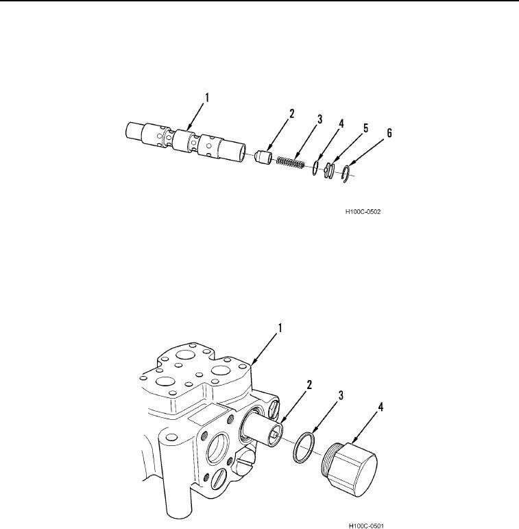
13. Lubricate new O-ring (Figure 16, Item 4) with technical petrolatum and install on plug (Figure 16, Item 5).
14. Install check (Figure 16, Item 2), spring (Figure 16, Item 3), and plug (Figure 16, Item 5) in lock plunger (Figure
16, Item 1). Hold plug down and install snap ring (Figure 16, Item 6).
Figure 16. Plunger Assembly.
0119
15. Lubricate new seal ring (Figure 17, Item 3) with technical petrolatum and install on cap (Figure 17, Item 4).
16. Install lock plunger assembly (Figure 17, Item 2) in control valve (Figure 17, Item 1).
17. Install cap (Figure 17, Item 4) on control valve (Figure 17, Item 1) and tighten securely.
Figure 17. Lock Plunger Installation.
0119
0119-10