
TM 5-3805-255-14
0119
ASSEMBLY CONTINUED
000119
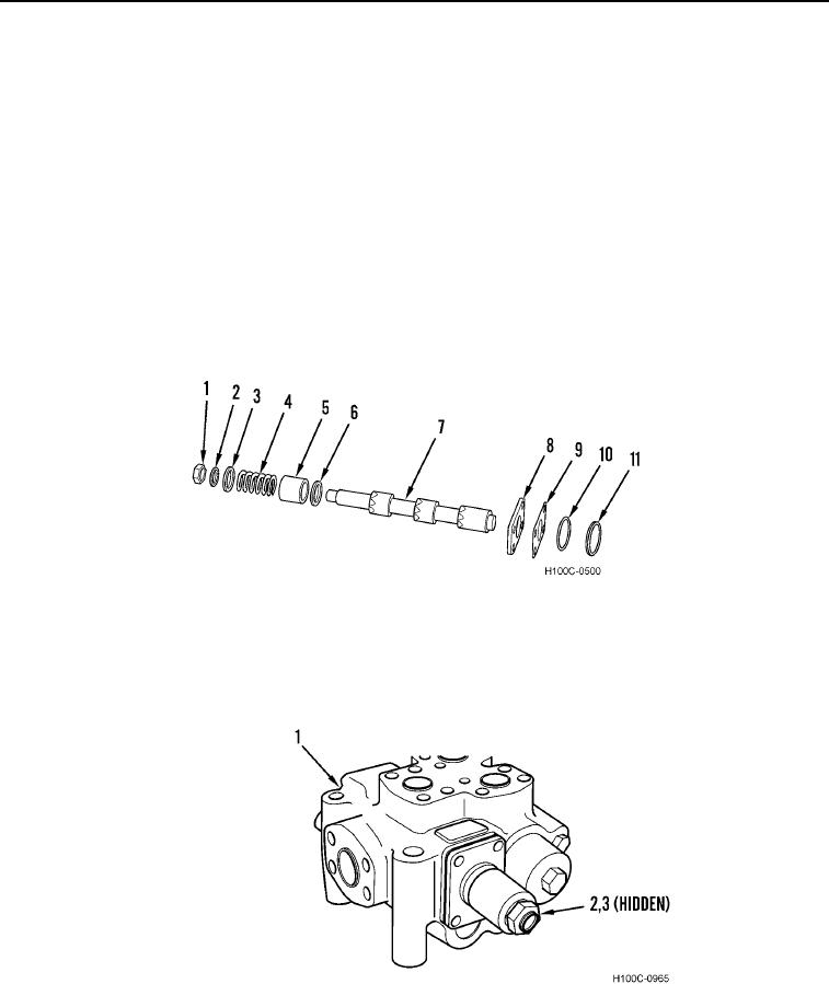
18. Lubricate new seal (Figure 18, Item 11) and control plunger (Figure 18, Item 7) with technical petrolatum.
NOTE
Word "OUTSIDE", molded into seal, must face toward threaded end of plunger. DO NOT
push seal onto plunger past first land.
19. Install seal (Figure 18, Item 11) on plunger shoulder (Figure 18, Item 7) at threaded end of plunger. Use shim
stock on plunger to avoid damage to sealing lip of seal.
20. Slide backup ring (Figure 18, Item 10), shim pack (Figure 18, Item 9), and spacer (Figure 18, Item 8) on
plunger shoulder (Figure 18, Item 7). Be careful not to break backup ring.
21. Assemble spacers (Figure 18, Items 5 and 6), spring (Figure 18, Item 4), spacer (Figure 18, Item 3), and
washer (Figure 18, Item 2) on plunger (Figure 18, Item 7).
22. Apply Loctite 242 sealant to plunger threads and assemble nut (Figure 18, Item 1) on plunger. Clamp plunger
in a vise between wooden blocks and tighten nut securely.
Figure 18. Control Plunger Assembly.
0119
23. Install control plunger (Figure 19, Item 2) in valve (Figure 19, Item 1) until shoulder with seal (Figure 19, Item 3)
is far enough into valve bore to allow seal to be pressed into seat of bore. DO NOT at any time allow seal to
move off plunger shoulder into groove.
Figure 19. Control Plunger Installation.
0119
0119-11