grease and glaze by wiping with a cloth saturated
with brake fluid. This in most instances will elimi-
nate squeak and extend the service life of the belts.
Check Hydraulic System for Leaks: Check oil
reservoirs, valve, pumps, cylinders, all hydraulic
h o s e lines and connections for leaks, correcting
w h e r e necessary. Particular attention should be
paid to hoses on the intake or suction side of the
p u m p s . Hose clamps and connections employed
must be securely tightened to prevent entrance of
foreign material or air into the system. Air drawn
into the system at this point will cause cavitation
o f the pump with resultant malfunctioning and
early failure. All hoses should be checked for abra-
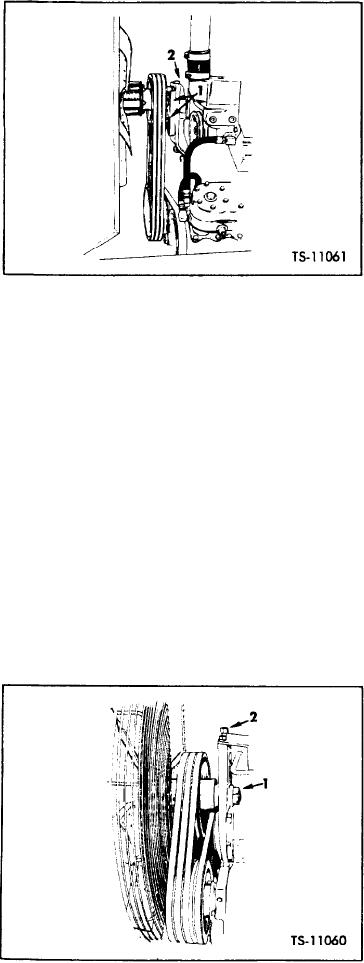
2. Adjusting Bolt
1. Mounting Bolts
sions which could result in ruptures of same. Re-
place hoses found in this condition.
Fig. 12. Check Fan Belt Tension - G.M.
bracket as shown in Figure 13.
Clean Torque Converter and Transmission
B r e a t h e r : The torque converter and transmission
2. Turn fan drive pulley adjusting bolt clockwise
system is equipped with a breather located on top
to raise fan drive pulley (increasing belt ten-
of torque converter.
s i o n ) or counterclockwise to lower fan drive
pulley (decreasing belt tension) depending on
E a c h 50 operating hours unscrew breather,
the existing condition.
wash in solvent, blow dry with compressed air and
reinstall.
3. Turn the adjusting bolt so that 7/16 inch maxi-
mum deflection is obtained on the belts midway
C h e c k Lights and Fuses: Two fuses provide
between the pulleys.
protection for the electrical system, one in gauge
circuit and one in light circuit. An additional self
4 . When belts are properly adjusted, retighten
contained fuse which is part of the lighter base and
locknut to 400-500 ft.-lbs. torque. Rotate torque
cord assembly provides protection for the lighter
one more hex.
element. All fuses are located behind the instru-
ment panel as shown on the Wiring Diagram.
5. Back-off adjusting screw one-half turn.
The light circuit fuse and gauge circuit fuse are
Periodically belts should be cleaned to remove
contained in plastic connectors. Push and twist to
open and lock plastic connectors for fuse replace-
ment. The self contained lighter fuse is a screw on
type fuse secured between the lighter base and cord
assembly.
To replace fuses remove instrument panel
mounting bolts and swing panel outward.
The circuits and fuse protection are :
Gauge Circuit . . . . . . . . . . . . . AGC 3/4 Amp.
Light Circuit . . . . . . . . . . . . . .SFE 20 Amp.
Lighter Circuit . . . . . . . . . . . . . . . . 10 Amp.
(a) Headlamps and Back-Up Lamps: The ma-
c h i n e is equipped with headlamps and back-up
1. Locknut
2. Adjusting Bolt
lamps mounted in shock resistant rubber retainers.
Fig. 13.
Check Fan Belt Tension - Cummins
[45-02-2]

