If stall rpm is not within specifications, trouble
shooting of engine or torque converter by a quali-
fied mechanic is required. See Specifications and
Service Data.
Note: Stall rpm specified in Specifications and
Service Data at rear of this manual is applicable
to altitude of 600 ft. and ambient temperature of
7 0 F . Do to many combinations of altitude and
temperature possible in the field, space does not
p e r m i t publishing here all the corrections neces-
s a r y to the stall rpm indicated to accommodate
such variations. It is suggested the engine manu-
f a c t u r e r ' s distributor be contacted to determine
the correction necessary for altitude and tempera-
ture in your application.
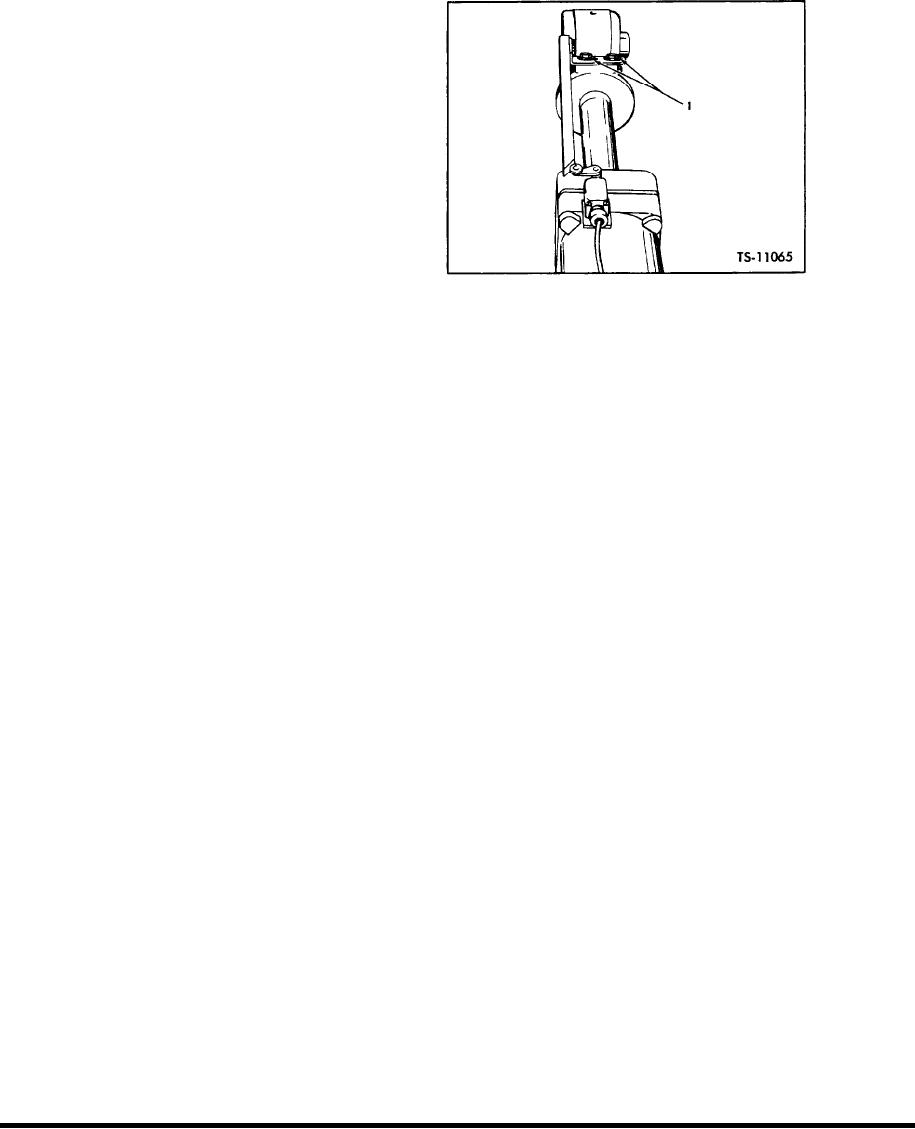
Adjust Bucket Leveler
Fig. 16.
Adjust Bucket Leveler: The bucket leveler
bucket is in a level position.
mechanism consists of a leveler cam and an electric
4. Additional adjustment is provided at the roller
switch mounted on the right hand bucket cylinder,
arm on the electric switch. Maximum stroke of
a n d a solenoid operated air valve. The electric
roller arm is 9/16 inch.
switch is wired to the solenoid operated air valve,
which in turn is connected to the air tank and main
5. Start engine. Raise bucket to a number of dif-
hydraulic valve by piping.
ferent heights and cycle bucket slowly at each
of these various heights to check proper opera-
The roller arm on the electric switch rolls off
tion. Each time bucket is rotated back from the
the leveler cam as the bucket is rotated back from
D U M P position, the bucket lever should return
the DUMP position. This action closes the electric
automatically to the HOLD (neutral) position.
switch and completes the circuit, sending a flow of
electricity to the solenoid operated air valve. This
releases a flow of air from the tank to the main
Adjust Boom Kickout: The boom kickout mech-
control valve causing the bucket lever to move from
anism consists of a boom cylinder mounted kickout
the detent located CLOSE position to the HOLD (neu-
cam, a frame mounted electric switch and solenoid
tral) position. The bucket will then stop in a level
mounted at the control valve boom spool.
position.
To obtain maximum height kickout switch
S e r v i c i n g and adjustment procedures are as
bracket should be installed in bottom slots of frame
follows : Refer to Figure 16 for correct position of
bracket. The roller on the electric switch should
leveler cam in relation to roller on electric switch
j u s t contact cylinder mounted kickout cam. This
when bucket is in a level position.
will cause boom kickout to occur at approximately
1 foot (30,5 cm) from maximum height. Lower
Caution: Leveler cam must be parallel to bucket
boom kickout positions may be obtained by raising
cylinder rod at all times.
switch bracket in mounting slots.
1. Start engine, position bucket level on ground,
Bleed Brake System: Occasionally it may be
shut down engine and pull bucket lever into de-
n e c e s s a r y to bleed brake system to remove air
tent located CLOSE position.
trapped in the system due to a leak in the line or
t h e installation of new parts in the system. Air
2. Adjustment is provided at the leveler cam
trapped in the system will be indicated by a soft
bracket. Elongated holes in the leveler cam
spongy brake pedal.
b r a c k e t allow adjustment either in or out to
m a i n t a i n proper roller arm stroke, l/8 inch to
Note: It is recommended to use a bleeder hose
actuate. (Figure 16 Item 1).
on bleeder values whenever possible to keep fluid
3. The roller on the electric switch should be just
a w a y from linings. Keep master cylinder(s) filled
off, but nearly touching the leveler cam when
during bleeding process.
[45-04-2]

