Engine Equipment
HYDRAULIC STARTING SYSTEM (HYDROSTARTER)
pressure is forced out of the accumulator, by the
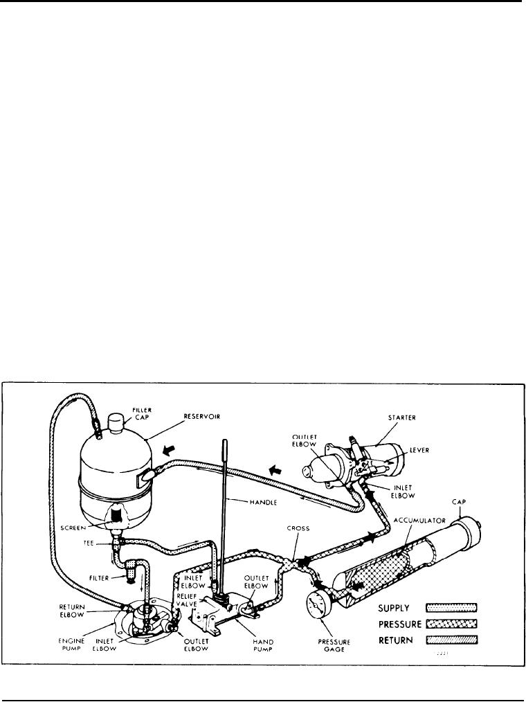
The hydrostarter system schematically illustrated in
expanding nitrogen gas, and flows into the starting
Fig. 9 is a complete hydraulic system for starting
motor which rapidly accelerates the engine to a high
internal combustion engines. The system is automati-
cranking speed. The used fluid returns directly to the
cally recharged after each start, and can be manually
recharged. The starting potential remains during long
reservoir from the starter.
periods of inactivity. and continuous exposure to hot
or cold climates has no detrimental effect upon the
The engine-driven charging pump runs continuously
hydrostarter system. Also, the hydrostarter torque for
during engine operation and automatically recharges
a given pressure remains substantially the same
the accumulator. When the required pressure is
regardless of the ambient temperature.
attained in the accumulator, a valve within the pump
body opens and the fluid discharged by the pump is
The hydrostarter system consists of a reservoir, an
by-passed to the reservoir. The system can be
engine-driven charging pump, a hand pump, a piston
shutdown and the pressure in the accumulator will be
type accumulator, a starting motor and connecting
maintained.
hoses and fittings.
The precharge pressure of the accumulator is the
pressure o f the nitrogen gas with which the
Operation
accumulator is initially charged. This pressure must be
checked before the system pressure is raised for the
Hydraulic fluid flows by gravity, or a slight vacuum,
initial engine start. To check the precharge pressure,
from the reservoir to either the engine-driven pump
open the relief valve, on the side of the hand pump,
or the hand pump inlet. Fluid discharging from either
approximately 1/2 turn, allowing the pressure gage to
p u m p outlet at high pressure flows into the
return to zero. Close the relief valve and pump several
accumulator and is stored at 3250 psi (22 393 kPa)
strokes on the hand pump. The gage should show a
under the pressure of compressed nitrogen gas.
rapid pressure rise from zero to the nitrogen
precharge pressure, where it will remain without
When the starter is engaged with the engine flywheel
change for several additional strokes of the pump.
ring gear and the control valve is opened, fluid under
Fig. 9 - Schematic Diagram of Hydrostarter System Showing Oil Flow
Page 40

