Engine Equipment
TRANSMISSIONS
Problems relating to the repair and overhaul of these
This manual includes information on the lubrication
transmissions should be referred to an authorized
and preventive maintenance of the transmissions. It
also includes adjustment procedures covering some of
Detroit Diesel Allison Service Outlet.
the more common power transmissions.
POWER TAKE-OFF ASSEMBLIES
the throwout linkage to the "over center" or locked
The front and rear power take-off units are basically
position.
similar in design, varying in clutch size to meet the
requirements of a particular engine application.
Adjust the 8", 11-1/2" and 14" diameter clutches as
follows:
The power take-off unit is attached to either an
adaptor (front power take-off) or the engine flywheel
1. Disengage the clutch with the hand lever.
housing (rear power take-off). Each power take-off
unit has a single or double plate clutch. The drive
2. Remove the inspection hole cover to expose the
shaft is driven by the clutch assembly and is supported
clutch adjusting ring.
by a pilot bearing in the flywheel or the adaptor and
by two tapered roller bearings mounted in the clutch
3. Rotate the clutch, if necessary, to bring the clutch
housing.
adjusting ring lock within reach.
4. On the 8" and 11-1/2" diameter clutches, remove
Clutch Adjustment
the clutch adjusting ring spring lock screw and lock
from the inner clutch pressure plate and adjusting
These instructions refer to field adjustment for clutch
ring. Then, while holding the clutch drive shaft to
facing wear. Frequency of adjustment depends upon
prevent the clutch from turning, turn the clutch
the amount and nature of the load.
adjusting ring counterclockwise as shown in Fig. 13
and tighten the clutch until the desired pressure on the
To ensure a long clutch facing life and the best
outer end of the hand lever, or at the clutch release
performance, the clutch should be adjusted before
shaft (Fig. 16). is obtained as shown in Table 1.
slippage occurs.
5. On the 14" diameter single and double plate
When the clutch is properly adjusted, a heavy pressure
clutches, raise the end of the adjusting ring lock up out
is required at the outer end of the hand lever to move
of the splined groove in the hub of the outer clutch
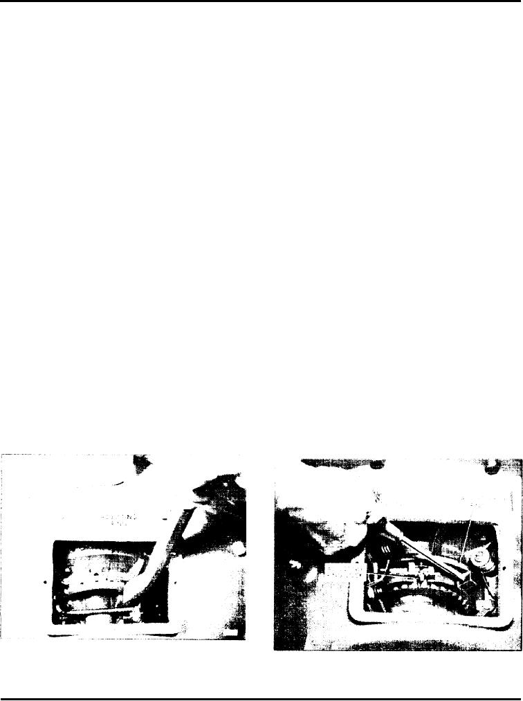
Fig. 13 - Power Take-Off Showing Typical 8
Fig. 14 - Power Take-Off Assembly Showing
and 11-1/2 Inch Diameter Clutch Adjustment
14 Inch Diameter Clutch Adjustment Ring
Ring
Page 47

