Engine Tune-Up
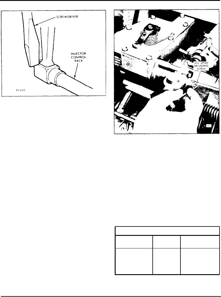
Fig. 4 - Checking Injector Control Rack
"Spring"
8. Insert the clevis pin in the fuel rod and the left bank
injector control tube lever. Repeat the check on the 1L
and 1R injector rack control levers as outlined in
Step 5. Carefully observe and eliminate any deflection
which occurs at the bend in the fuel rod where it
Fig. 5 - Adjusting Idle Speed
enters the cylinder head.
11. Insert the clevis pin in the fuel rods and the
9. To adjust the remaining injector rack control levers,
injector control tube levers.
remove the clevis pin from the fuel rods and the
injector control tube levers, hold the injector control
12. Use new gaskets and install the valve rocker covers.
racks in the full-fuel position by means of the lever on
the end of the control tube. and proceed as follows:
Adjust Maximum No- Load Engine Speed
a . Turn down the inner adjusting screw of the
All governors are properly adjusted before leaving the
injector rack control lever until the screw bottoms
factory. However, if the governor has been recondi-
(injector control rack in the full-fuel position).
tioned or replaced, and to ensure the engine speed will
not exceed the recommended no-load speed as given
b . Turn down the outer adjusting screw of the
on the engine option plate, set the maximum no-load
injector rack control lever until it bottoms on the
speed as outlined below.
injector control tube.
Start the engine and, after it reaches normal operating
c. While still holding the control tube lever in the
temperature, u s e an accurate hand tachometer to
full-fuel position, adjust the inner and outer
adjusting screws to obtain the same condition as
Variable Speed Governor Adjustment
outlined in Step 5. Tighten the screws.
Shims
Stops
Full-Load
Speed'
CAUTION: Once the No. 1L and No. 1R
injector rack control levers are adjusted, do not
Up to .325
2
1200-1750
try to alter their settings. All adjustments are
made on the remaining control racks.
in shims
I
1750-2100
10. When all of the injector rack control levers are
maximum
0
2000-2300
adjusted, recheck their settings. With the control tube
lever in the full-fuel position, check each control rack
No-load speed is 125-200 rpm above full-load speed depending
*
as in Step 5. All of the control racks must have the
upon engine application.
same "spring" condition with the control tube lever in
TABLE 1
the full-fuel position.
Page 109

