
Engine Tune-Up
VARIABLE SPEED HYDRAULIC GOVERNOR AND INJECTOR RACK CONTROL
ADJUSTMENT
6, 8 and 12V ENGINES
After adjusting the exhaust valves and timing the fuel
injectors, adjust the governor linkage (Fig. 1) and
position the injector rack control levers.
Adjust Governor Linkage and Position Injector
Rack Control levers
1. Clean and remove the valve rocker cover from each
cylinder head. Discard the gaskets.
2. Loosen all of the inner and outer injector rack
control lever adjusting screws. Be sure all of the
control levers are free on the control tubes.
3. Disconnect the vertical link assembly from the
governor operating lever and the hell crank.
4. Loosen the bolt and slide the governor operating
lever from the serrated shaft.
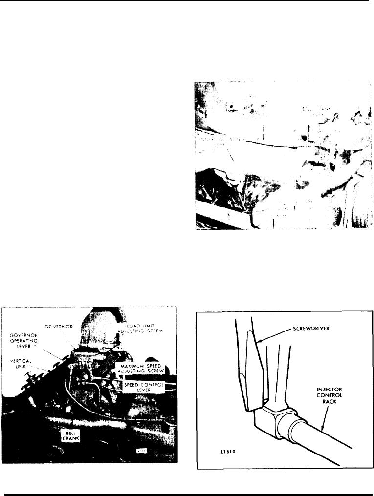
Fig. 2 - Positioning No. 1R Rack Control Lever
5. Place the bolt (removed from the lower end of the
vertical link) through the bell crank and into the
control tube (Fig. 2). Turn down the outer adjusting
recessed hole in the governor drive housing.
screw until it also bottoms on the control tube. Then
alternately tighten both the inner and outer adjusting
6. Adjust the No. 1R injector rack by turning the
screws.
inner adjusting screw down until it bottoms on the
Fig. 1 - Hydraulic Governor Mounted on
Fig. 3 - Checking Injector Rack "Spring"
Engine
Page 121