Engine Tune-Up
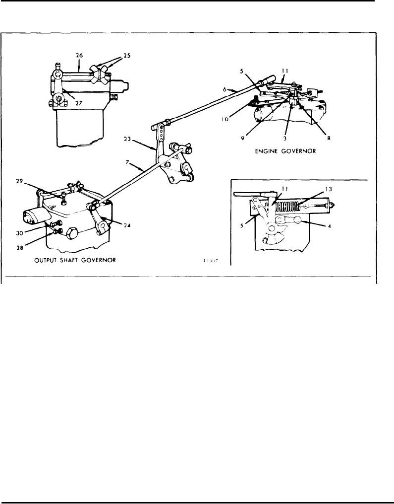
HYDRAULIC OUTPUT SHAFT GOVERNOR AND LINKAGE ADJUSTMENT
3. Lever--Throttle Control
8.
Pin--Stop
23 Lever--Throttle Control
27 Lever--Speed Control
4. Lever--Shutdown
9
Spring--Torsion
Rear Cross Shaft
28. Screw--Maximum Speed
5. Lever--Engine Governor
10
Bolt (Stop)
24. Lever--Output Shaft
Limit Adjusting
11
Lever--Output Shaft
29. Screw--Minimum Speed
Governor Control
Operating
Governor
Limit Adjusting
6. Rod--Engine Governor
25. Wing Nut--Speed
7. Rod--Output Shaft
13. Spring--Governor Lever
Adjusting
30. Screw--Maximum Fuel
Governor
Return
26 Link--Sliding
Adjusting
Fig. 1 - Hydraulic Output Shaft Governor and Linkage
A hydraulic governor is used to maintain a near
constant output shaft speed. The output shaft speed
constant output shaft speed on engines equipped with
will be constant up to full power of the engine, except
a Series 500 or larger Torqmatic converter. The
for the amount of governor droop. The speed setting
governor is mounted on the converter and gear driven
of the engine governor must be sufficiently higher than
from the output shaft.
the speed setting of the output shaft governor so the
engine governor will not reduce the fuel input to the
engine before full power is required by the output
The output shaft governor is connected to the engine
shaft governor. As load is applied to the output shaft,
governor by control rods and levers (Fig. 1). The
the output shaft speed will decrease gradually up to
control rod end ball joints are sealed assemblies and
the amount of the output shaft governor droop at full
do not require lubrication. Other moving parts of the
load. At the same time, the engine speed will gradually
control linkage should be lubricated with engine oil.
increase until full load is reached.
In most applications, such as drag line and shovel
operation, it is desirable to have the output shaft
In some types of operation, such as laying of structural
steel, it is desirable to operate the unit with a very low
governor control the fuel input to maintain a relatively
Page 148

