Engine Tune-Up
Not more than one unit in a system of paralleled
alternators with engines controlled by centrifugal
governors can be operated on "zero" droop.
If necessary, adjust the speed droop as follows:
1. Start the engine and run it at approximately half-
load until the lubricating oil temperature is stabilized;
governor regulation will become more stable as the oil
temperature increases.
2. Stop the engine and remove the actuator cover.
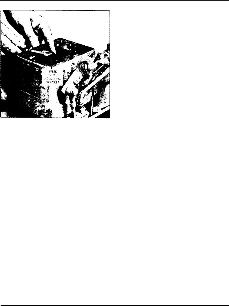
3. Loosen the speed droop adjusting bracket screw and
move the bracket (Fig. 7) slightly to obtain the desired
droop; moving the bracket toward the flyweight end of
the actuator will increase the droop. Tighten the screw.
4. Install the actuator cover and, with the engine
running, adjust the speed until the engine is operating
at the desired speed above the rated full-load speed.
5. Apply the full rated load on the engine and readjust
the speed to the correct full-load speed.
Fig. 7 - Adjusting Speed Droop
6. Remove the rated load and note the engine speed
after it stabilizes under no load. If necessary, stop the
droop adjustment has no effect on operation and
engine, remove the actuator cover and readjust the
should be left as factory set. When, for some reason,
speed droop bracket.
the centrifugal governor section is controlling the
engine, the speed droop setting can be adjusted, if
After the engine tune -up is completed, reconnect the
necessary, to suit the operating requirements. The
electrical circuit of the governor at the receptacle on
governor should never be set at "zero" droop unless
the actuator cover. If necessary, refer to the
the unit is maintaining the frequency of paralleled
Woodward Governor Company's Bulletin 37709 for
alternators or is operating as a single, isolated unit.
the procedures to be followed in checking the electrical
system.
16V ENGINE
The tune-up procedure for a 16V engine equipped
the variable speed hydraulic governor (6. 8 and 12V)
with the EG-B electric governor is similar to the
or in the variable speed hydraulic governor (16V). The
procedure used on the 6, 8 or 12V engines. To position
governor adjustments, however, are the same as on the
the injector rack control levers, use the same linkage
6, 8 and 12V engines.
gage (J 22195) but follow the procedure outlined in
Page 144

