
28. Remove two bolts and lock washers that secure air
chamber bracket to axle housing; remove bracket
and spacers (Fig. 28).
1/32" DIA RADIUS ALL CORNERS
TS-5685
FIG. 30
29. Disassemble opposite side of axle following instruc-
tions given in steps 2 through 28.
30. If axle is equipped with parking brake, proceed as
indicated below. If axle is not equipped with parking
brake, proceed to step 39. Position socket on flange
nut and then install flange retaining tool with two
spacers between tool and flange. Spacer dimensions
are given in Fig. 30. loosen flange nut (Fig. 29). Re-
move flange retaining tool and remove flange nut
and washer.
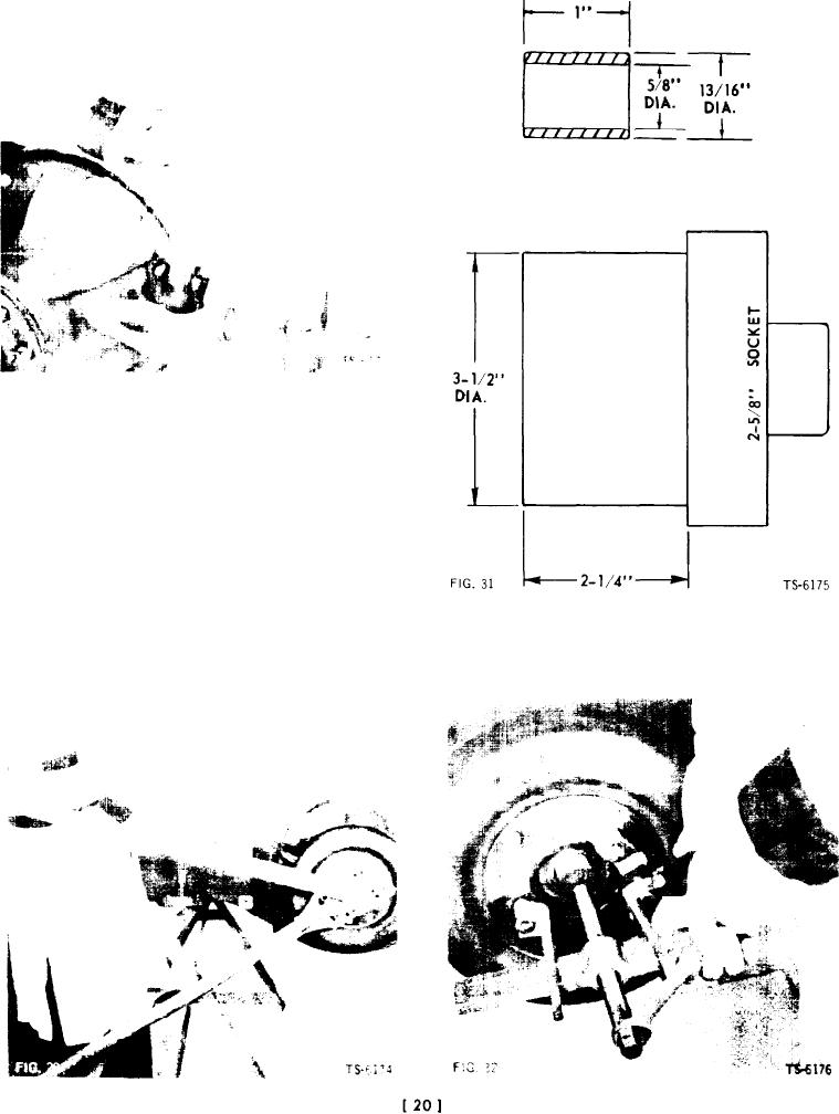
31. Use suitable puller to pull assembled companion
NOTE: Standard 2 5/8 -inch socket will not fit flange nut
flange and parking brake drum from pinion shaft
because socket wall is too thick to enter recess in
(Fig. 32).
flange. Machine socket as shown in Fig. 31 to provide
proper clearance.