
DISASSEMBLY AND ASSEMBLY
OF THE TYRONE POWER SENSOR
Clean the outside of the pump and valve thorough-
ly before beginning disassembly. Choose a clean
working area and make sure that you have all the
necessary tools. The tools necessary to disassem-
ble and service this valve are:
Combination Wrench Set
Magnet
Allen Wrench Set
Hand Stone
Screw Driver
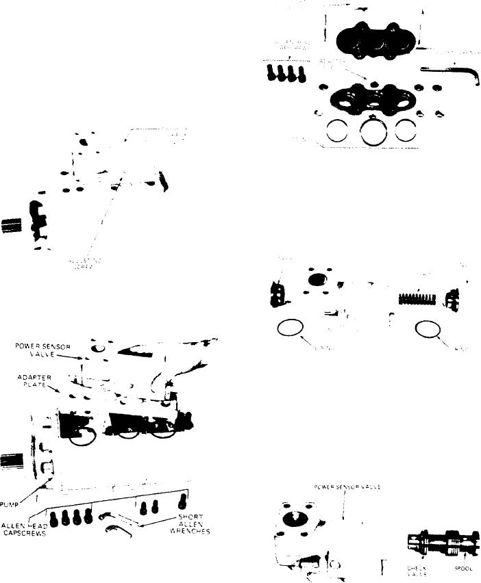
3 . Separate the adaptor plate from the valve by
removing the four allen head capscrews. Note
the position of O-rings.
1. Punch mark the adapter plate and pump so that
they can be assembled in the proper position.
4. Remove the two large plugs and O-rings from
t h e valve. Hold the valve in a vice with soft
jaws while removing these plugs. Remove spring
from valve.
2. R e m o v e the power sensor valve and adaptor
p l a t e from the pump. Use a shortened allen
wrench to remove allen head capscrews holding
the adaptor plate to the pump.
Note the position of O-rings. Set the pump
5. Remove spool from valve in the direction shown
a s i d e and place the valve and adaptor plate on
in the picture. Do not force the spool. Rotate
a clean working surface.
the spool while removing it.
[44]