
ASSEMBLY OF THE VALVE
Examine all parts for wear and dirt. Pay special
attention to the spool and bore in the valve. Make
certain that the spool slides freely within the bore
of the valve. Replace all parts that show any signs
of damage. The spool valve may be replaced only if
the bore in the valve is in good condition.
Thoroughly clean all parts for reassembly. Use
new O-rings and coat them with light grease.
Torque cap screws as follows:
6. Examine the spool very carefully for nicks,
burrs, foreign material and rust. If the spool
SIZE
shows any signs of wear or damage, replace it.
40-45 lbs/ft.
3/8 - 16 NC
P a y special attention to the surfaces of the
65-80
l bs/ft.
7/16 - 14 NC
check valve and seat on the spool.
85-100 lbs/ft
1/2 - 13NC
When installing the adjusting screw, turn it into
the casting only about three revolutions.
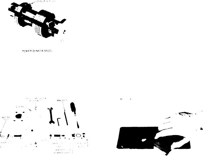
8. Make certain that all surfaces of the valve, the
7. Remove the two remaining plugs and O-rings
adaptor plate and the pump housing are clean
from the valve. Remove the acorn nut, lock nut,
and free of dirt. Use a fine stone to remove any
adjusting screw and O-rings. Remove the plug
burrs, as shown in the picture. Assemble the
and O-ring that cover poppet seat. Use a screw-
valve in a sequence opposite to disassembly.
driver to remove the poppet seat and washer.
Refer to page 200 for adjusting procedures and
Use a magnet to remove the poppet, spring and
spring guide.
troubleshooting guide.
[45]