
DISASSEMBLY AND ASSEMBLY
OF THE TYRONE POWER STEERING VALVE
Clean the outside of the pump and valve
thoroughly before beginning disassembly. Choose
a clean working area and make sure that you have
a l l the necessary tools. The tools necessary to
disassemble and service this valve are:
Combination Wrench Set
Allen Wrench Set
Hand Stone
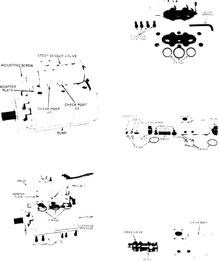
3 Separate the adaptor plate from the valve by,
removing the four allen head capscsrews. Note
the position of O-rings.
1. Punch mark the valve, adaptor plate and pump so
that they can be reassembled in the proper pos-
ition.
4. Remove the two small plugs and O-rings from
the valve. Remove the acorn nut, locknut, ad-
j u s t i n g screw and O-rings. Remove the large
plug that contains the adjusting screw and the
O-ring. Remove the two spring guides and the
spring from the valve. Remove the remaining
large plug and O-ring from the valve.
2. Remove the power steering valve and adaptor
p l a t e from the pump, use a shortened allen
wrench to remove alien head capscrews hold-
i n g the adaptor plate to the pump. Note the
5. Remove the spool from the valve in the direc-
p o s i t i o n of O-rings, set the pump aside and
t i o n shown in the picture. Do not force the
place the valve and adaptor plate on a clean
spool. Rotate the spool while removing it.
working surface.
[46]