TM 5-3805-258-24-1
9904 DIRECT INJECTION VEHICULAR ENGINE
SPECIFICATIONS
WITH SCROU FUEL SYSTEM
(1)
(2)
(3)
(4)
(5)
(6)
(7)
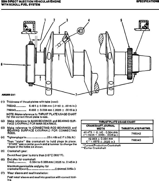
CRANKSHAFT
Thickness of thrust plstee with tsbs (new):
7N9342 . . . . . . . . . . . . . .
5,461 t 0.036 mm (.2150 * .0015 in.)
7N9343 . . . . . . . . . . . . . .
6.655 * 0.038 mm (.2620 * .0015 in.)
NOTE: Make reference to THRUST PLATE USAGE CHART
for the correct thrust plate to use.
Make reference to MAIN BEARINGS and BEARING SUR-
FACE (JOURNAL) FOR MAIN BEARINGS.
Make reference to CONNECTING ROD BEARINGS and
BEARING SURFACE (JOURNAL) FOR CONNECTING
RODS.
Tighten pluga to . . . . . . . . . . . . . . . . . . . . 23 ~ 4 N.m (17 * 3 Ib.ft.)
Then “stake” the crankshaft to hold plugs in place.
“STAKE” uses center punch and a hammer to change the
ahape of the holes as shown.
Crankshaft gear:
Do not heat gear to more than 316°C (600”F).
End play for crankshaft
(new) . . . . . . . . . . . . . . . . .
0.064 to 0.366 mm (.0025 to .0145 in.)
Maximum permissible end play for
crankshaft (worn) . . . . . . . . . . . . . . . . . . . . . . . . . . . . . . 0.64 mm (.025 in.)
Wear sleeve and seal installation:
Push wear aleeve and seal into position with correct tool-
ing.
r
THRUST PLATE USAGE CHART
I
CRANKSHAFT JOURNAL
WIDTH
THRUST PLATE PART NO.
40.475 + 0.140-0.064 mm
(” 1.5935 + .0055 -.0025 in.)
7N9342
I
42.863 t 0.064 mm
(*• 1.6875 f .0025 in.)
I
7N9343
‘1
“Current Production Crankshaft
‘ l Earlier Crankshaft
2-20