3304 DIRECT INJECTION VEHICULAR ENGINE
WITH SCROLL FUEL SYSTEM
TM 5-3805-258-24-1
SPECIFICATIONS
(1)
(2)
(3)
CYLINDER LINER
Bore in liner
(new) . . . . . . . . . . . . . . . . . 120.68 t 0.03 mm (4.751 f .001 in.)
Use again maximum bore when measured
near upper end of the wear surface of the
cylinder liner . . . . . . . . . . . . . . . . . . . . . . . . . . . . . . . . . . . . . . 120.78 mm (4.755 in.)
Thickness of flange
on liner . . . . . . . . . . . . . . 10.282 t 0.020 mm (.4048 ~ .0008 in.)
Filler band.
Cylinder liner Installation
Put liquid soap on bottom liner bore in block, on grooves in lower liner,
and on O-rings. Install O-rings on liner. Put filler band (3) in engine oil for
a moment and install on liner. Immediately install liner in cylinder block
(before expansion of filler band).
CYLINDER LINER PROJECTION
Make reference to CYLINDER LINER PROJECTION in Testing and
Adjusting for the complete procedure.
1. Install gasket and spacer plate (2) with bolts (3) and two 1 S379
Washers. Tighten bolts (3) evenly in four steps:
1st step . . . . . . . . . . . . . . . . . . . . . . . . . . . . . . . . . . . . . . . . . . . . . . . . . . . . . . . 14 Nm (10 Ib.ft.)
2nd step . . . . . . . . . . . . . . . . . . . . . . . . . . . . . . . . . . . . . . . . . . . . . . . . . . . . . . 35 N.m (25 Ib.ft.)
3rd step . . . . . . . . . . . . . . . . . . . . . . . . . . . . . . . . . . . . . . . . . . . . . . . . . . . . . . . 70 N.m (50 Ib.ft.)
4th step . . . . . . . . . . . . . . . . . . . . . . . . . . . . . . . . . . . . . . . . . . . . . . . . . . . . . . . 95 N.m (70 Ib.ff.)
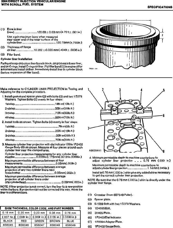
2. Install tools as shown. Tighten bolts (4) evenly in four steps:
1st step . . . . . . . . . . . . . . . . . . . . . . . . . . . . . . . . . . . . . . . . . . . . . . . . . . . . . . . . . . . 7 N.m (5 Ib.ft.)
2nd step . . . . . . . . . . . . . . . . . . . . . . . . . . . . . . . . . . . . . . . . . . . . . . . . . . . . . . 20 N.m (15 Ib.ft.)
3rd step . . . . . . . . . . . . . . . . . . . . . . . . . . . . . . . . . . . . . . . . . . . . . . . . . . . . . . . 35 N.m (25 Ib.ft.)
4th step . . . . . . . . . . . . . . . . . . . . . . . . . . . . . . . . . . . . . . . . . . . . . . . . . . . . . . . 70 N.m (50 Ib.ft.)
3. Measure cylinder liner projection with dial indicator (6) in 1P2402
Gauge Body (8) as shown. Measure at four places around each
cylinder liner near the clamped area.
Cylinder liner projection measurements for any cylinder liner
must be . . . . . . . . . . . . . . . . . . . . . 0.033 to 0.175 mm (.0013 to .0069 in.)
Maximum permissible difference between all four
measurements . . . . . . . . . . . . . . . . . . . . . . . . . . . . . . . . . . . . . . . . . . . . 0.05 mm (.()()2 in.)
Maximum permissible difference between average
projection of any two cylinder liners next
to each other . . . . . . . . . . . . . . . . . . . . . . . . . . . . . . . . . . . . . . . . . . . . . 0.05 mm (.002 in.)
Maximum permissible difference between average
projection of ail cylinder liners under
one cylinder head . . . . . . . . . . . . . . . . . . . . . . . . . . . . . . . . . . . . . . . 0.06 mm (.003 in.)
NOTE: If liner projection is not correct, turn the liner to a new position
within the bore. If projection can not be corrected this way, move the
liner to a different bore.
I
SHIM THICKNESS, COLOR CODE, AND PART NUMBER
I
~
(.007
in.)
(.008 in.)
(.009 in.) (.oI5 in.) (.o3o in.)
4. Minimum permissible depth to machine counterbore to
adjust
cylinder
liner
projection
.
.
.
0.76
mm
(.030
in.)
Maximum permissible depth to machine counterbore to
adjust cylinder liner projection . . . . . . . . . . . . . . . . . . . . 1.14 mm (.045 in.)
Install a 0.76 mm (.030 in.) shim plus any added shims necessary
to get the correct cylinder liner projection.
NOTE: Be sure that the 0.76 mm (.030 in.) shim is directly under the
cylinder liner flange.
(1)
(2)
(3)
(4)
(5)
(6)
(7)
(8)
Crossbar (from 8B7548 Puller).
Spacer plate.
S 1589 Bolt with two 1 S379 Washers.
1 D4595 Bolt.
3H465 Plate.
1 P2403 Dial Indicator.
1 P2394 Adapter Plate.
1 P2402 Gauge Body.
2-17