TM 5-3805-258-24-1
950B HYDRAULIC SYSTEM
SPECIFICATIONS
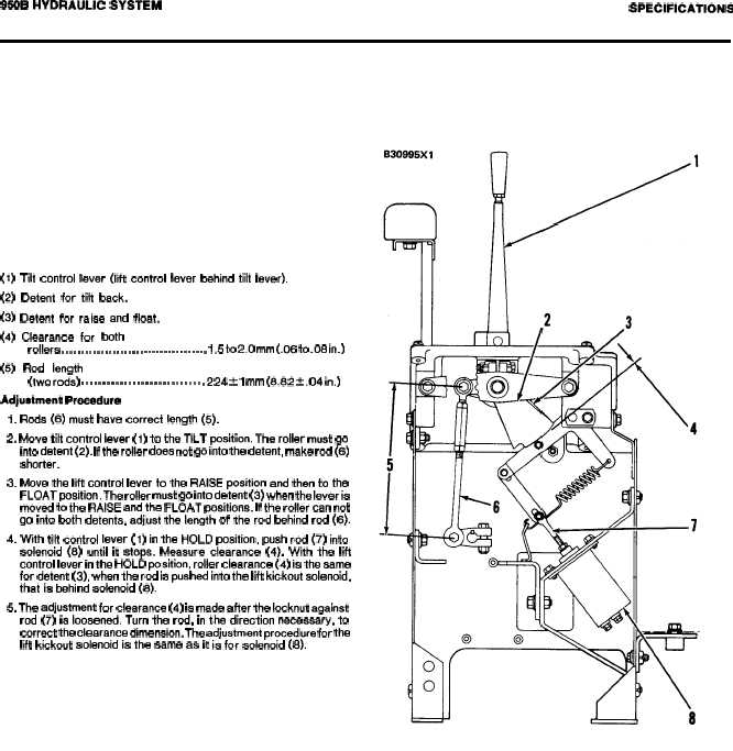
CONTROL LEVER LINKAGE
(1) Tilt control lever (lift control lever behind tilt lever).
(2) Detent for tilt back.
(3) Detent for raise and float.
(4) Clearance for both
rollers . . . . . . . . . . . . . . . . . . . . . . . . . . . . . . . . . . . . . 1.5 to 2.0 mm (.06 to .08 in.)
(5) Rod length
(two rods) . . . . . . . . . . . . . . . . . . . . . . . . . . . . . 224 * 1 mm (8.82 f .04 in.)
Adjustment Procedure
1. Rods (6) must have correct length (5).
2. Move tilt control lever (1) to the TILT position. The roller must go
into detent (2). If the roller does not go into the detent, make rod (6)
shorter.
3. Move the lift control lever to the RAISE position and then to the
FLOAT position. The roller must go into detent (3) when the lever is
moved to the RAISE and the FLOAT positions. If the roller can not
go into both detents, adjust the length of the rod behind rod (6).
4. With tilt control lever (1) in the HOLD position, push rod (7) into
solenoid (8) until it stops. Measure clearance (4). With the lift
control lever in the HOLD position, roller clearance (4) is the same
for detent (3), when the rod is pushed into the lift kickout solenoid,
that is behind solenoid (8).
5. The adjustment for clearance (4) is made after the locknut againat
rod (7) is loosened. Turn the rod, in the dtrection necessary, to
correct the clearance dtmension. The adjustment procedure for the
lift kickout solenoid is the same as it is for solenoid (8).
2-69