TM 5-3805-258-24-1
9SOB HYDRAULIC SYSTEM
SPECIFICATIONS
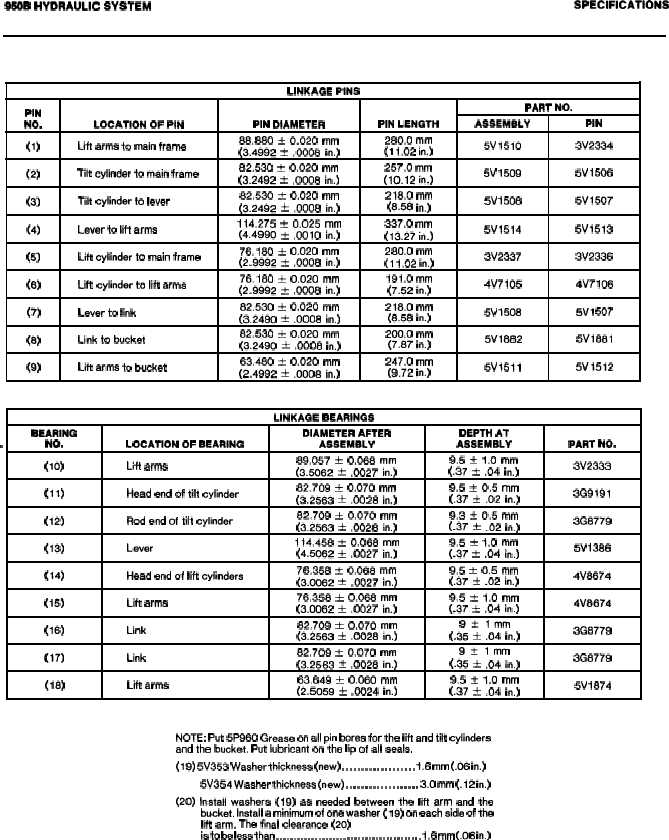
BUCKET CONTROL GROUP
LINKAGE PINS
PIN
PART NO.
NO.
LOCATION OF PIN
PIN DIAMETER
PIN LENGTH
ASSEMBLY
PIN
(1)
Lift arms to main frame
88.880 * 0.020 mm
280.0 mm
(3.4992 & .0008 in.)
(1 1.02 in.)
5V151O
3V2334
(2)
Tilt cylinder to main frame
82.530 k 0,020 mm
257.0 mm
(3.2492 * .0008 in.)
(10.12 in.)
5V 1509
5V
1508
(3)
Tilt cylinder to lever
82.530 k 0.020 mm
218.0 mm
(3.2492 * .0008 in.)
(8.58 in.)
5V 1508
5V1507
(4)
Lever to lift arma
114.275 ? 0.025 mm
337.0 mm
(4.4990 * ,0010 in.)
(13.27 in.)
5V1514
5V1513
(5)
Lift cylinder to main frsme
76.180 ~ 0.020 mm
280.0 mm
(2.9992 f .0008 in.)
(1 1.02 in.)
3V2337
3V2336
(6)
Lift cylinder to lift arms
76.180 t 0,020 mm
191.0 mm
(2.9992 f .0008 in.)
(7.52 in.)
4V7105
4V7 106
(7)
Lever to link
82.530 ~ 0.020 mm
218.0 mm
(3.249o ? .0008 in.)
(8.58 in.)
5V 1508
5V1 507
(8)
Link to bucket
82.530 ~ 0.020 mm
200.0 mm
(3.2490 + .0008 in.)
(7,87 in.)
5V1882
5V1681
(9)
Lift arma to bucket
63.480 h 0.020 mm
247.0 mm
(2.4992 & .0008 in.)
(9.72 in.)
5V1511
5V1512
LINKAGE BEARINGS
BEARING
DIAMETER AFTER
NO.
DEPTH AT
.
LOCATION OF BEARING
ASSEMBLY
ASSEMBLY
PART NO.
(lo)
Lift arms
89.057 * 0.068 mm
9.5 ? 1.0 mm
(3.5062 t .0027 in.)
(.37 * .04 in.)
3V2333
(11)
Head end of tilt cylinder
82.709 t 0.070 mm
9.5 * 0.5 mm
(3.2563 t .0028 in.)
(.37 * .02 in.)
3G9191
(12)
Rod end of tilt cylinder
62.709 * 0.070 mm
9.3 * 0.5 mm
(3.2563 & .0028 in.)
(.37 * .02 in.)
3G8779
(13)
Lever
114.458 ~ 0.068 mm
9.5 ? 1.0 mm
(4.5062 ~ .0027 in.)
(.37 * .04 in.)
5V 1386
(14)
Head end of lift cylinders
76.358 & 0.068 mm
9.5 * 0.5 mm
(3.0062 * .0027 in.)
(.37 * .02 in.)
4V8674
(15)
Lift arms
76.358 ~ 0.068 mm
9.5 * 1.0 mm
(3.0062 ~ .0027 in.)
(.37 t .04 in.)
4V8874
(16)
Link
82.709 * 0.070 mm
9~lmm
(3.2563 & .0028 in.)
(.35 * .04 in.)
3G8779
(17)
Link
82.709 k 0.070 mm
9*lmm
(3.2563 * .0028 in.)
(.35 * .04 in.)
3G8779
(18)
Lift arms
83.849 h 0.060 mm
9.5 * 1.0 mm
(2.5059 ~ .0024 in.)
(.37 * .04 in.)
5V 1874
NOTE: Put 5P960 Grease on all pin bores for the lift and tilt cylinders
and the bucket. Put lubricant on the lip of all seals.
(19) 5V353 Washer thickness (new) . . . . . . . . . . . . . . . . . . . 1.6 mm (.06 in.)
5V354 Washer thickness (new) . . . . . . . . . . . . . . . . . . . 3.0 mm (.12 in.)
(20) Install washers (19) as needed between the lift arm and the
bucket. Install a minimum of one washer ( 19) on each aide of the
lift arm. The final clearance (20)
is to be less than . . . . . . . . . . . . . . . . . . . . . . . . . . . . . . . . . . . . . . . . . 1.6 mm (.06 in.)
2-72


