TM 5-3805-258-24-1
H Y D R A U L I C
S Y S T E M
S Y S T E M S
O P E R A T I O N
If the pressure of the oil in the circuit through inlet
opening (1) and in the chamber for spring (9) gets as
high as the setting of the relief valve, the oil moves
pilot valve (3) open. The oil in the spring chamber
goes, through the open pilot valve and through pas-
sage (8) to the tank. Now, with only the force of
spring (9) on valve (2), the pressure of the oil in inlet
opening (1) moves valve (2) far enough to let the oil
in the inlet opening (and circuit) go through outlet
openings (7) to the tank. When the oil in the circuit
can go through inlet opening (1) and then through
outlet openings (7), the pressure of the oil can not
increase to a pressure higher than the setting of the
relief valve.
The pressure setting of the relief valve can be
changed by either an increase or a decrease in the
force of the spring that keeps pilot valve (3) closed.
Remove plug (6) and turn plunger (5) clockwise for
an increase or counterclockwise for a decrease in the
pressure setting of the relief valve.
Relief Valves For Tilt And Attachment
Cylinders
There is a relief valve in each of these circuits:
head end of the tilt cylinder, rod end of the tilt
cylinder, head end of attachment or third cylinders
and rod end of attachment cylinders. These valves
are the same in construction and operation. These
valves are different in construction from the main
relief valve, but their operation is similar.
When either valve spool (tilt control or third con-
trol) is in HOLD position, the relief valves in the
head and rod ends limit the maximum amount of
pressure in the cylinder lines. If an outside (external)
force on the bucket or attachment becomes too high,
the relief valve will permit movement of the cylinder
piston. This prevents damage to the machine
components.
The relief valve for the rod end of the tilt cylinder
also releases the rod end pressure when the lift arms
are lifted with the bucket fully dumped and the tilt
control valve spool is in HOLD position.
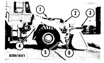
BUCKET CONTROL GROUP
The bucket control group gives a way to control the
operation of bucket (3). This group is made up of
two lift cylinders (4), one tilt cylinder (1), lift arm
assembly (5), lever (2) and link (6). This type of
linkage is known as Z-bar linkage because of the Z
formed by the tilt cylinder, lever and link. Tilt cy-
linder (1), lift cylinders (4) and lift arm assembly (5)
are fastened to the loader frame by pins.
B U C K E T C O N T R O L G R O UP
1. Tilt cylinder. 2. Lever. 3. Bucket. 4. Lift cylinders (in-
side loader frame). 5. Lift arm assembly. 6. Link (between
the lift arm assembly).
When pressure oil is sent to the head end of the lift
cylinders, lift arm assembly (5) is lifted. When pres-
sure oil goes to the rod end of the lift cylinders (4),
the lift arm assembly is lowered.
The bucket will tilt back when pressure oil is sent
to the head end of tilt cylinder (1). The bucket will
dump when pressure oil goes to the rod end of the tilt
cylinder.
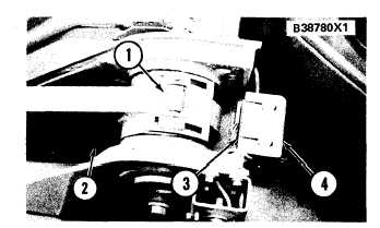
LIFT KICKOUT
P A R T S T O A C T I V A T E T H E L I F T K I C K O U T
1. Magnet assembly. 2. Lift arm on left side. 3. Electric
switch in the holder. 4. Holder for electrical switch.
3-109