H Y D R A U L I C
S Y S T E M
lever is moved to the TILT BACK position, the
spring for the tilt control, beside spring (7) moves the
roller into detent (6) which keeps the control lever in
the TILT BACK position.
TM 5-3805-258-24-1
S Y S T E M S O P E R A T I O N
system. The oil then goes through lift and tilt control
valve (26) because both valve spools are in HOLD
position. The oil then goes through oil filters (29) and
back into hydraulic tank (18). If oil filters (29) get
full of foreign material (debris), filter bypass valve
(28) will open and let the return oil go directly into
the hydraulic tank.
When the tilt control lever is moved to TILT
BACK position, tilt back stem (12) moves to TILT
BACK position. Pilot oil is now free togo through lift
and tilt pilot valve (5) to the left end of tilt valve spool
(13). This causes the tilt valve spool to move to the
right. The pilot oil at the right end of tilt valve spool
(13) goes back to lift and tilt pilot valve (5), through
C O N T R O L L E V E R S A N D L I N K A G E
I N H O L D P O S I T I ON
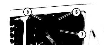
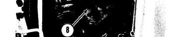
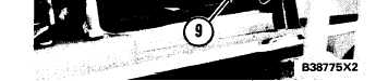
5. Detent for lift and float. 6. Detent for tilt back. 7. Spring
(for lift detent roller). 8. Lift kick out solenoid. 9. Bucket
positioner
solenoid.
TILT CIRCUIT
TILT BACK Operation
When the engine is running with the control levers
in HOLD position, pilot pump section (19) takes oil
from hydraulic tank (18) and sends it first to pilot
section relief valve (17) which controls the maximum
pressure in the pilot system. The pilot oil flow then
divides. Some oil goes through line (16) to the hand
metering unit of the steering system. Some oil goes
through check valve (15) and selector and pressure
control valve (10) to lift and tilt pilot valve (5). The
valve stems in the pilot valve stop the flow of oil in
HOLD position. The oil from pilot pump section (19)
goes through pilot section relief valve (17) through
oil filters (29) and back into hydraulic tank (18).
At the same time, steering pump section (20)
sends oil through line (23) to the steering control
valve of the steering system. Also, implement pump
section (27) sends oil to main relief valve (4) which
controls the maximum pressure in the implement oil
dump stem (11) and on to hydraulic tank (18).
The movement of tilt valve spool (13) stops the
flow of oil through lift and tilt control valve (26).
Implement pump pressure increases and opens load
check valve (9). The oil from implement pump sec-
tion (27) now goes to the head end of tilt cylinder (1)
and causes the cylinder piston and rod to extend. The
Z-bar linkage causes the bucket to tilt back. The
movement of the cylinder piston and rod pushes the
oil out of the rod end of the tilt cylinder. This oil
comes into lift and tilt control valve (26) and goes
around both valve spools (13) and (22) on its way
back to oil filters (29) and hydraulic tank (18).
There is a detent in TILT BACK position when
the bucket is between DUMP position and the cor-
rect angle to dig. This detent holds the tilt control
lever [and tilt back stem (12)] in TILT BACK posi-
tion until the bucket gets to the correct angle to dig.
When the bucket gets to the correct angle, the bucket
positioner releases the tilt control lever and the lever
and tilt back stem (12) go back to HOLD position.
The flow of pilot oil through lift and tilt pilot valve
(5) is stopped. The springs on tilt valve spool (13)
move the valve spool back to HOLD position. The
pilot oil at the left end of the tilt valve spool goes back
to lift and tilt pilot valve (5), through tilt back stem
(12) and on to hydraulic tank (18). The implement
oil in tilt cylinder (1) is held by tilt valve spool (13)
and movement of the cylinder piston and rod stops.
The bucket will stay at the correct angle to dig until
the tilt control lever is moved again. There is no
detent from the digging angle to tilt back. The con-
trol lever must be held in TILT BACK position to
move the bucket farther.
See FO-1, STANDARD HYDRAULIC SYSTEM IN TILT BACK POSITION, located in the back of this manual.
3-111