TM 5-3805-258-24-1
H Y D R A U L I C
S Y S T E M
S Y S T E M S O P E R A T I O N
The lift kickout is electric and its action moves the
lift control lever from the detent on the RAISE posi-
tion to the HOLD Position just before the lift arms
get to the top of their travel.
When the rods in the lift cylinders, that move the
lift arms, get near their full extension, magnet (1) on
the left side lift arm (2) goes toward holder (4).
Switch (3), in holder (4) on the loader frame, is a
solid state switch. The magnet (field) closes the
switch to make a ground in the switch. The ground is
for the circuit of lift kickout solenoid (8). As the lift
arms are moved higher, magnet (1) moves under
switch (3) and the magnet (field) closes the circuit in
the switch, for solenoid (8). Now that solenoid (8)
has a closed circuit, the solenoid activates and pulls
the roller away from detent (5). With no roller in the
detent to keep the lift control lever in the RAISE
position, the spring in the pilot valve moves the lift
stem and the lift control lever to the HOLD position.
With the lever and lift stem in the HOLD position,
the movement of the lift cylinder rods stop before the
pistons on the rods hit the ends of the lift cylinders.
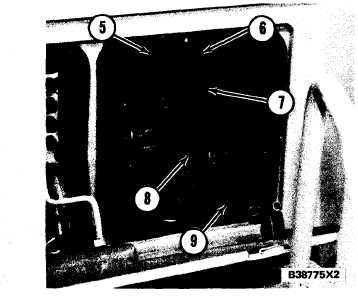
C O N T R O L L E V E R S A N D L I N K A G E
I N H O L D P O S I T I O N
5. Detent for lift and float. 6. Detent for tilt back. 7. Spring
(for lift detent roller.) 8. Lift kickout solenoid. 9. Bucket
positioner
solenoid.
When magnet (1) closes the circuit in switch (3), it
is not closed very long and the circuit for lift kickout
solenoid (8) is again open. The solenoid releases the
roller when the circuit is open. Now, spring (7) will
move the roller into detent (5), to hold the lift control
lever in a position, when it is moved to either RAISE
or FLOAT position. Magnet (1) must move away
from switch (3) and then be moved under switch (3)
again to close the switch (circuit), but only for ap-
BUCKET POSITIONER
The bucket positioner is electric. Its action moves
the tilt control lever from the detent on the TILT
BACK position to the HOLD position at the correct
angle to dig as the bucket moves from dump to tilt
back.
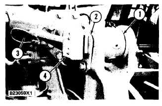
P A R T S T O A C T I V A T E T H E B U C K E T P O S I T I O N ER
( T Y P I C A L)
1. Rod. 2. Magnet assembly (on tilt lever arm). 3. Tilt
cylinder. 4. Electric switch (in cover assembly on the tilt
c y l i n d e r ) .
The rod moves farther out of the tilt cylinder to
move the bucket away from dump to bucket tilt back.
When rod (1) moves out of tilt cylinder (3), magnet
(2) on the tilt lever goes toward bucket positioner
switch (4). Switch (4), in the bucket positioner
switch assembly on tilt cylinder (3), is a solid state
switch. In one direction (toward tilt back), the mag-
net (field) closes the switch to make a ground for the
solenoid circuit. In the other direction (toward
dump), the magnet (field) opens the switch to open
the circuit (no ground).
As the tilt cylinder rod moves the bucket from
dump toward tilt back, magnet (2) moves almost past
switch (4) and the magnet (field) closes the circuit
for bucket positioner solenoid (9). Now that solenoid
(9) has a closed circuit, the solenoid activates and
pulls the roller away from detent (6). With no roller
in the detent to keep the tilt control lever in TILT
BACK position, the spring in the pilot valve moves
the valve stem and the tilt control lever to the HOLD
position. Now, the movement of the tilt cylinder rod
stops and the movement of the bucket stops at the
correct angle to dig. Solenoid (9) keeps activated and
there is no detent for the TILT BACK position of the
tilt control lever. The lever must be held in any
position except HOLD.
When the rod moves into the tilt cylinder to move
the bucket from tilt back to dump, magnet (2) moves
past switch (4). The magnet (field) opens the circuit
to solenoid (9) when it passes switch (4) and the
proximately one-half second.
solenoid is not activated. Now, when the tilt control
3-110