TM 5-3805-258-24-1
S Y S T E M S O P E R A T I O N
O P E R A T O R ’ S S T A T I ON
I N D I V I D U A L
C I R C U I T
D E S C R I P T I ON
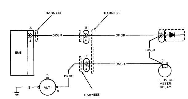
B. Alternator
This circuit has a connection from the “R” terminal of the alternator to
Pin 3 of the operator panel. When the main key switch is in the ON
position but the engine is not running, the alternator indicator on the
operator panel will be ON.
The “R” terminal is also connected to the service meter relay. This will
energize when the engine is running and not allow the engine start relay to
energize when the key start switch is turned ON, causing possible damage
to the starter motor.
When the engine is running, the alternator indicator will be OFF if the
alternator output is high enough.
A L T E R N A T O R
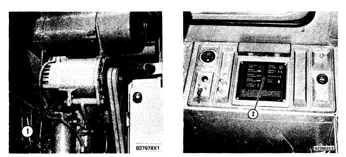
1. Alternator.
A L T E R N A T O R
I N D I C A T O R
2. Alternator indicator.
A l t e r n a t o r O u t p u t C i r c u it
3-151