POWER TRAIN
TRANSMISSION HYDRAULIC
3. Install slug (6) in the end of valve spool (7).
Install spring (5) on the end of valve spool (7).
TM 5-3805-258-24-2
DISASSEMBLY AND ASSEMBLY
CONTROL VALVES
4. Install stop (8) and dowel (10) in the valve
body.
5. Install spring (5) and valve spool (7) as shown.
Install the stop (not showing) and dowel (9) to
hold the valve spool, slug and spring in position.
6. Install stop (11) and dowel (12) in the valve
body.
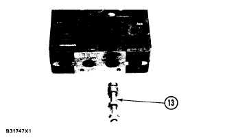
7. Install ball (14), spring (15), retainer (16) and
ring (17) in valve spool (13). Install slug (18) in
valve spool (1 3).
8. Install the slug and valve spool (13) in the valve
body as shown.
5-259


