TM 5-3805-258-242
VEHICLE SYSTEMS
DISASSEMBLY AND ASSEMBLY
LOADER CONTROL VALVES
INSTALL LOADER CONTROL VALVES 5051-12
Tools Needed
A
8S7641
Tube
2
8S7630
Stand
2
8S8048
Saddle
2
8S7615
Pin
2
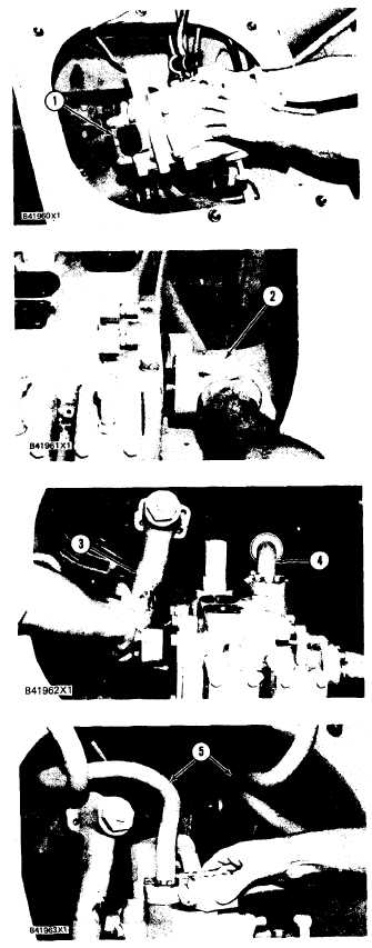
1. Install a ½’’- 13 NC forged eyebolt and a 3/8”-
16 NC forged eyebolt in loader control valves
(1) as shown. Fasten a hoist to the valves.
2. Putthevalves imposition andinstall the bolts
that hold the valves to the machine.
3. Inspect all O-ring seals for wear or damage.
Make replacements if necessary.
4. Put the O-ring seals in position in tube assem-
blies (2). Install the flanges and bolts.
5. Connect hose assembly (4) and manifold (3) to
the control valves.
6. Connect tube assemblies (5) to the control
valves.
7. Connect the top of the tube assemblies to the
brackets on the machine.
5-328

