VEHICLE SYSTEMS
TM 5-3805-258-24-2
DISASSEMBLY AND ASSEMBLY
SHUTTLE
REMOVE AND INSTALL SHUTTLE VALVE
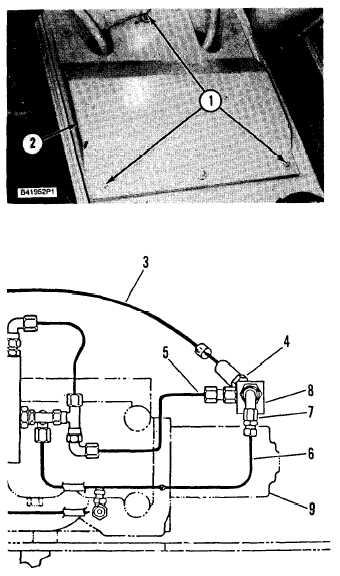
1. Remove nuts (1) and cover (2) from the
machine.
WARNING
To prevent personal injury, release the pressure
from the hydrauIic system before any lines are
removed or discarded.
2.
3.
4.
5.
6.
7.
8.
9.
10.
11.
12.
13.
Place identification labels on all hose and
tube assemblies that are removed.
Disconnect hose assembly (3) from tee (4).
Disconnect tube assembly (5) from other
side of tee (4).
Disconnect tube assembly (6) from elbow
(7).
Unscrew shuttle valve (8) from coupling on
hydraulic control valve (9).
Remove tee (4) and elbow (7) from valve (8).
To install shuttle valve (8), screw valve onto
coupling on the hydraulic control valve (9).
Install tee (4) and elbow (7).
Connect tube assembly (6) at elbow (7).
Connect tube assembly (5) to tee (4).
Connect hose assembly (3) to tee (4).
Start the engine and operate the attachment
(third) control lever. Check for leakage of
hydraulic fluid from fittings. If there is no
leakage, install cover (2) and nuts (1).
VALVE
5-325


