VEHICLE SYSTEMS
TM 5-3805-258-24-2
DISASSEMBLY AND ASSEMBLY
PILOT AND HYDRAULIC PUMP
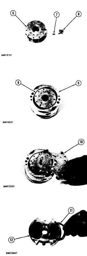
6. Install inserts (7) and vanes (8) in rotor (6).
The sharp edge of the vanes must be in the
same direction as the arrow on the rotor.
7. Put rotor assembly (9) in position in ring (5).
Make sure that the sharp edge of the vanes and
the arrow on the chamfer are in the same direc-
tion.
8.
9.
Put plate (10) in position on the cartridge
assembly. Make sure the brass side of the plate
is toward the rotor assembly. Also make sure
the notches on outside diameters of plates (4)
and (10) are in alignment. Make an alignment
of these notches with the chamfers on ring (5).
Put the O-ring seals in position in the plastic
seals. Install seal assemblies (11) on plate (12)
with the O-ring side of seal toward plate (12).
5-403

