TM 5-3805-258-24-2
VEHICLE SYSTEMS
DISASSEMBLY AND ASSEMBLY
PILOT AND HYDRAULIC PUMP
ASSEMBLE PILOT AND
HYDRAULIC PUMP
5073-16
Tools Needed
A
B
1P510
Driver Group
1
1P1859
Snap Ring Pliers
1
1. Inspect all parts for wear or damage. Make
replacements if necessary. Put clean oil on all
parts of assembly.
NOTE: For correct assembly of the parts the pump
rotation is in a clockwise direction as seen from the
pilot end of the hydraulic pump.
2.
3.
4.
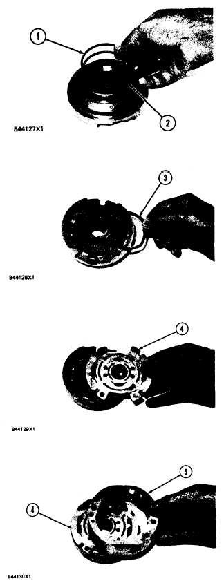
Install O-ring seal (2) and then seal ring (1) on
the end plate.
Put the O-ring seals in position in the plastic
seals. Install seal assemblies (3) on the end
plate with the O-ring seal toward the plate.
Put plate (4) in position so the brass side is
toward the rotor.
5. Put ring (5) on plate (4) as shown. The arrow
on the chamfer of ring (5) must be in the same
direction of the rotation of the rotor.
5-402

