VEHICLE SYSTEMS
39.
40.
41.
42.
43.
44.
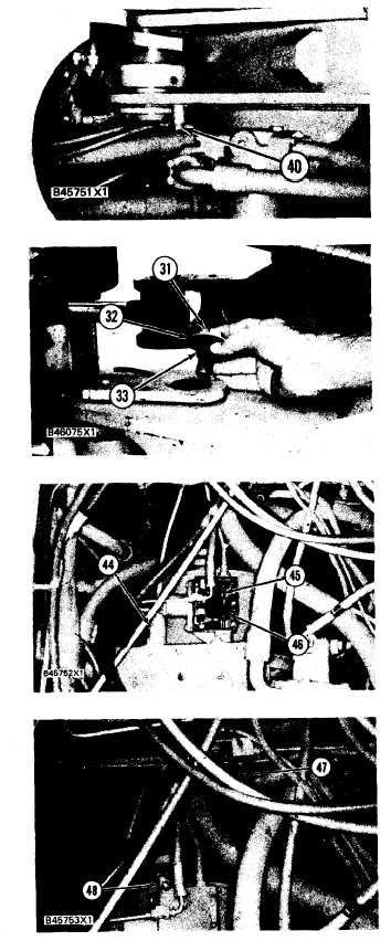
Install bolt (40) that holds the clip and cable
assemblies to the frame.
Remove tooling (F) and install bolts (43) to the
frame.
Connect clips (41) that hold the hose assem-
blies to the frame.
Connect clip (42) that holds the wire assembly
to the frame.
Make sure O-ring seal is in position and con-
nect transmission selector cable (44) in the
notch (slot) on the valve spool.
Connect cable assembly (45) to cam (46) in the
transmission neutralizer group.
Make an adjustment to the transmission neu-
tralizer
control.
See POWER SHIFT
TRANSMISSION TESTING AND AD-
45.
JUSTING.
LOADER MAIN FRAMES
Models 950BNS and 950BS
46. Connect tube assemblies (47) and (48).
47. Remove all tooling from the machine.
TM 5-3805-258-24-2
DISASSEMBLY AND ASSEMBLY
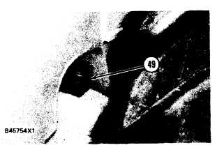
48. Remove blocks (49) from between the axle
housing and rear frame.
end by:
a) install center drive shaft
b) install cab and platform
c) separation of anti-pivot link
5-475