TM 5-3805-258-24-2
VEHICLE SYSTEMS
DISASSEMBLY AND ASSEMBLY
LOADER MAIN FRAMES
Models 950 BNSCE and 950BSCE
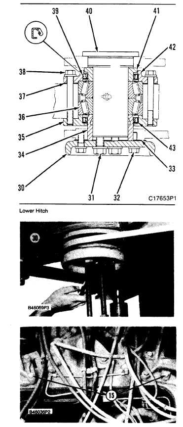
20. Install pin (40) in the lower hitch assembly. Install
spacer (34).
21. Position shims (33) and plate (30). Install two of
bolts (31), 180° apart. If the holes in cap (30) and the
holes in the frame are not in alignment, use two 5/8” -
11 NC guide bolts to turn cap (30) and the pin as
shown. Tighten the bolts to 68 N•m (50 Ib.ft.).
22. Measure the gap with a feeler gauge 360° around
between the lower front frame and plate (30). Install
shims (33) needed of minimum measurement minus
0.25 mm (.010 in.) under plate (30).
23. Install all of bolts (31) and (32), and tighten them.
24. Disconnect the hoist and tooling (C), and install
bolts (15).
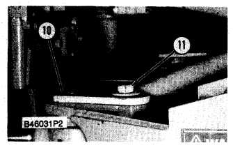
25. Make an alignment of the steering cylinders to the
front frame, Install pins (30). Install the spacers,
washers and bolts (11) that hold the pins in place.
5-476j


