TM 5-3805-262-20
3-24. ACCESSORIES TROUBLESHOOTING (CONT)
MALFUNCTION
TEST OR INSPECT ION
CORRECTIVE ACTION
8. DEFROSTER MOTOR DOES NOT OPERATE (Cont).
S t e p 6 . ( C o n t ) .
Carefully pull cab switch panel upwards from heater console just
enough to gain access to 6 ampere circuit breaker terminals.
Disconnect light green wire spade terminal from 6 ampere circuit
breaker terminal.
Turn ignition key switch to on position and press 6 ampere circuit
breaker button.
Check if defroster motor operates.
a . I f d e f r o s t e r m o t o r o p e r a t e s,
s h o r t c i r c u i t e x i s t s i n r e a r d e f o g -
ger fans. Isolate problem to defective fan by disconnecting wire
first from one fan, checking if circuit breaker blows, and then
repeating for remaining fan. Replace fan if necessary (page
10-62) .
b. If 6 ampere circuit breaker blows again, problem is in DEFROSTER
s w i t c h , r e s i s t o r , o r d e f r o s t e r m o t o r . I s o l a t e t o d e f e c t i v e p a r t
by disconnecting wire from defroster motor, then resistor, and
f i n a l l y d e f r o s t e r s w i t c h. Replace defective part (page 10-52 or
10-58) .
Step 7.
With ignition key switch in on position, check if rear defogger fans
o p e r a t e .
a. If rear defogger fans do not operate, replace 6 ampere circuit
breaker (page 10-58).
b. If rear defogger fans operate, go to step 8 below.
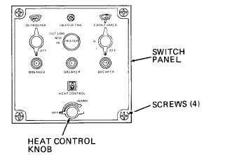
Step 8.
Turn ignition key switch to off position.
Remove HEAT CONTROL knob from cab switch panel by pulling straight
up off control shaft .
Remove four screws securing cab
switch panel.
Carefully pull switch panel
upwards from heater console
just enough to gain access to
DEFROSTER switch terminals.
Connect multimeter between DE-
FROSTER switch M terminal and
c h a s s i s.
Turn ignition key switch to on
p o s i t i o n.
Multimeter shall indicate 24
v o l t s .
a. If 24 volts not obtained, replace DEFROSTER switch (page 10-58).
3-172