TM 5-3805-262-20
3-24. ACCESSORIES TROUBLESHOOTING (CONT)
MALFUNCTION
TEST OR INSPECTION
CORRECTIVE ACTION
6. CAB HEATER FAN NOT OPERATING (Cont).
S t e p 4 . ( C o n t ).
b. If multimeter indicates 24 volts , a short circuit to ground
e x i s t s i n c a b e l e c t r i c a l c i r c u i t . I s o l a t e d e f e c t i v e c i r c u i t b y
reconnecting wire from cab relay BAT. terminal to long, silver
terminal of cab circuit breaker. Then, at cab switch panel,
disconnect and tape wires connected to each of the three circuit
breakers one at a time and check if remaining circuit(s) operate
when associated switch is operated.
If circuit is okay, problem
is in circuit associated with breaker from which wire was dis-
connected.
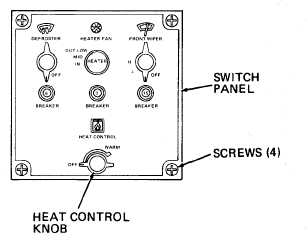
Step 5. Press 3 ampere circuit breaker just below HEATER FAN switch on cab
switch panel.
Check if heater fan operates.
a. If heater fan operates, problem was momentary short in circuit.
If circuit breaker blows, a short to ground exists in circuit.
Isolate by checking wiring for worn insulation. If wiring okay,
perform resistance check of heater fan. Replace parts as neces-
sary (page 10-28).
b. If heater fan does not operate, go to step 6 below.
Step 6.
Turn ignition key switch to off
p o s i t i o n .
Remove HEAT CONTROL knob from
cab switch panel by pulling
s t r a i g h t u p o f f c o n t r o l s h a f t.
Remove four screws securing cab
switch panel.
Carefully pull cab switch panel
upwards from heater console just
enough to gain access to HEATER
FAN switch terminals.
Connect multimeter between
HEATER FAN switch terminal to
which orange-black wire con-
nected and chassis.
Turn ignition key switch to on position.
Multimeter shall indicate 24 volts.
a. If 24 volts not obtained, replace 3 ampere circuit breaker (page
10-48).
3-167


