TM 5-3805-262-20
3-31. FUEL SYSTEM TROUBLESHOOTING (CONT)
MALFUNCTION
TEST OR INSPECTION
CORRECTIVE ACTION
1. LOW FUEL PRESSURE (Cont).
Step 1.
O p e n r a d i a t o r g r i l l e a t r e a r o f l o a d e r.
Connect STE/ICE power cable W5 connector P1 to VTM J1.
Check that VTM PUSH ON/PULL OFF switch is in OFF position.
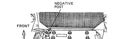
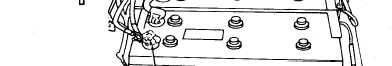
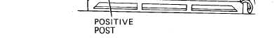
Connect power cable W5 red clip lead to loader
and black clip lead to loader battery negative
b a t t e r y p o s i t i v e p o st
post.
Remove engine right side panels (page 9-14).
L o o s e n a n d d i s c o n n e c t t u b e f i t t i n g s f r o m e l b o w s i n s t a l l e d i n f u el
injection pump feed pump and filter head. Be careful not to bend or
kink tube.
Loosen and remove elbows from fuel injection pump feed pump and fil-
t e r h e a d.
Install barb hose elbow connector in filter head port .
Install tee in fuel injection pump feed pump port.
Install barb hose straight connector in one port of tee .
Put two hose clamps on ends of 1/4 inch inside diameter hose.
Connect hose between barb hose connectors installed in filter head
and fuel injection pump feed pump. Do this by pushing end of hose
firmly onto barb hose connector.
P o s i t i o n h o s e c l a m p s o v e r e a c h e n d o f h o s e a t t a c h e d t o b a r b h o se
connector and tighten .
I n s t a l l p r e s s u r e t r a n s d u c e r ( b l u e s t r i p e , T K i t e m 1 7 ) i n t e e i n -
stalled in fuel injection pump feed pump port.
Connect transducer cable W4 connector P1 to VTM J2.
Connect transducer cable W4 connector P2 to transducer connector.
3-245